This is the
PIAS module to define, and manage the hullform, an to apply it for output and export. The notion of ‘hullform’ is interpreted rather wide in this module: it also contains related matters, such as openings, deck line and wind contour. The main menu of
Hulldef is depicted below, but before we get into the details of the program will we explain below first in general the hull form definition method.
Hulldef's hullform definition method
PIAS contains two modules for hull form definition. One is Fairway, which is designed for hull shape design and fairing, and which generates a closed hull surface. In addition, there is this module, Hulldef, where cross sections are entered. Although Fairway gives a much more complete and better result, working with Hulldef is in general faster. Because of the difference in objective, there is also a difference in hull shape representation method. Hull form representations contains a list of the representations used in PIAS, and there we read that Hulldef uses the frame model. Its main characteristics are:
More in detail the characteristics of Hulldef are:
- A hull form is defined on cross sections (or frames. The words cross sections, ordinates and frames are being used alternately in the manual they are considered to be synonymous) only. Buttocks and waterlines are not used.
- The advantage of this definition method is that it is very simple: basically, a body plan is just digitized. One drawback is in between the frames nothing exists, so no intermediate frames can be interpolated. However, in the calculations this plays no role, PIAS is fully optimized for this definition method.
- The number of frames is up to the user, although there are some guidelines, which are discussed in Number of frames. Frame distances are basically free, although there is a limit on very uneven spacing, see Ratio of longitudinal frame distances for details.
- Longitudinal discontinuities are defined by using a two coinciding frames at that location. Examples of longitudinal discontinuities are the transition from to forecastle and the forward and aft sides of deck house, moonpool or hatch coaming, see Double frames for examples.
- If no special settings have been made, only a demi ship needs to be defined, which is assumed to be symmetrical, so that the other half is identical, but mirrored. That half the ship is located to starboard, so transverse coordinates are positive. Of course, there are facilities for asymmetric ships and so on, but those are the exceptions.
- The frame shape is defined counter clockwise. So, in general starting at the bottom, at centreline, and then in outward/upward in the direction of the deck edge. Basically, this continues until the frame is closed, at centreline at the top. But in practice it is often more convenient to stop at the deck edge, and to let the upper part (with the deck, or perhaps a hatchway or superstructure) be generated automatically using an appendage. Refer to Appendages for that.
- More detailed tips are presented in Frames (frame positions and frame shapes).
- All hydrostatical and stability calculations (and the like) in PIAS are based on this frame model.
- Attention
- Although the frame model is a sufficient basis for the calculations, it does not contain any information about the shape of the hull in between the defined frames. As a result, on output the shape of a longitudinal line or an intermediate frame might seldomly not be drawn accurately. However, this is no reason for concern, as these lines do not play any role in the calculations.
Input, edit and view general particulars and hull geometry data
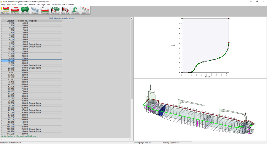
Input window for main particulars and hull geometry.
With this option an input window appears, from which an example is depicted above. This window consists out of three sub-windows, from which the leftmost is used for alphanumerical data entry, the window top right for the graphical representation of one particular type of data and the window at the bottom right to show all data types as managed by Hulldef simultaneously, graphically and in 3D. For options in the 3D window reference is made to the last section of this chapter, notably the orientation box which provides a tool to assist in the proper viewing direction, see View. With the top bar icons, the appropriate input subject can be selected, which can alternatively be achieved with a function keys-control combination, where <ctrl><F1> equals the activation of the leftmost icon, etcetera, until <ctrl><F9> for the rightmost icon. Anyway, the different subjects are:
The menu bar contains, besides the common function, an additional [Visible] function, which can be used to specify which of the data elements as managed by this module (such as wind contour, openings and deck line) will be visible in the right-under three-dimensional representation window.
Define main dimensions and further ship parameters
In this menu the general particulars of the ship can be given. These belong to the ship data definition, therefore this menu is included in this hull definition module Hulldef, and also in the hull form design and fairing module Fairway, see Define main dimensions and other ship parameters. Here only ship data are included, program settings, on the other hand, can be defined in Config. This module is subdivided into sub menus for the different categories:
Main dimensions and allowance for shell and appendages
- Ship name, the project name, or the name of the vessel. This name will appear on all printed output.
- Length between perpendiculars. The trim is based on this length.
- Moulded beam, on the construction waterline.
- Draft, the moulded draft at LPP/2 on the construction waterline. As a rule, for sea-going vessels>24 meter the summer draft according to the Load Lines Convention.
- Dredging draft, the draft with reduced freeboard, as could be applicable for hopper dredgers. for details please refer to daarover Stability of open hopper vessels.
- Moulded depth, the minimum depth at side above base.
- Appendage coefficient, a multiplication factor for shell and appendages. In general, this factor has a value between 1.000 and 1.010. Please be advised that the common values for the appendage coefficient are for the effect of appendages and shell plate thickness. If a shell plate thickness is defined separately, the appendage coefficient may not include this shell effect.
- Mean shell plate thickness, which is used to determine the shell volume explicitly, and should be given in metres. The shell plate volume is determined offsetting the frame contours with the shell plate thickness, a method which leads to two effects. The first one is that the thickness of a transom or a flat and vertical stem is not taken into account. And the second effect is that the shell plate volume, contrary to the common shipbuilding practice, is added directly to the moulded volume.
Roll data (for Intact Stability Code weather criterion)
- Type of midship section: Round or sharp bilge.
- Projected area of (bilge-)keels: Total area in m2.
These parameters are used to determine the angle of roll in accordance with the Intact Stability Code 2008. Table 2.3.4-3, where for the factor AK the area entered here is substituted.
Frame spacings
This menu facilitates the definition of the (construction) frame numbers and also the frame numbers where the frame spacing changes. In each menu of PIAS where longitudinal distances are required it is an alternative to press function key <F3> and enter the frame number, which is converted into meters instantaneously. Please see that although <F3> will prove to be very convenient, it is only a local aid to convert frames to meters, all output and input of PIAS will still remain in meters or related units. There is also a somewhat more extended frame conversion utility, activated with <F4> — Input window contains more details on the use of <F3> and <F4>. With the data entered in these menus an entire frame table can also be printed, please see Frame location table for a discussion. The frame definition parameters as such are given the following submenu:
Define the frames where the frame spacing changes
Here the frame numbers (with a maximum of 150) can be entered where the frame spacing changes. The actual frame spacing can be defined at the next option, however, these ‘frames where frame spacing changes’ should be given first.
Define frames spaces
Here the frame spacings (in meters) can be specified, for each of the regions with a distinct frame spacing.
Define remaining frame spacing data.
The location of (construction) frame zero should be specified here, in meters, in PIAS' system of axes (see Definitions and units. With the aftmost and foremost frames, which should also be specified in this menu, the frame range is fixed, which is important when printing a frame location. Finally, it can be indicated whether or not the frame spacing information should be used.
Draft marks and allowable maximum and minimum drafts
In this menu the location of the draft marks — and other locations where the drafts must be calculated and checked — can be given, which may be applied at the calculation of loading conditions with Loading. A maximum of twenty locations can be defined, and for each location must be given:
- Name
- A free, textual description which is printed on the output for identification.
- Draft mark.
- Indicates whether this location is a draft mark. If this is not the case, it is any other location where the draft has to be checked.
- Check
- Indicates whether the draft at this location must be checked to a minimum or maximum allowable draft. If so, this can be further detailed with:
- Tmax global, where the mean draft is checked against the maximum as set in Loading. This Loading maximum is a type rather than a number, e.g. Summer Draft or Winter North Atlantic. This can be set with option [Settings] in the loading condition as discussed in Draft.
- Tmax local, where the draft at this mark is checked against the local maximum, as given for this mark.
- Tmin local, mutatis mutandis for the local minimum.
- Tmin and Tmax
- If with the previous option is set that the draft should be verified against a local minimum or maximum, then those can be given here.
- T ps/sb mean
- which indicates if the mean draft over PS/SB has to be calculated, checked and printed.
- Print paper
- ‘Yes’ or ‘no’, which indicates whether this mark should be included in output of Loading. In the majority of cases that will be desirable, however, occasionally one might wish to switch the mark ‘off’.
- Print screen
- Which, similar to the previous option, indicates whether this mark should be printed on screen in the GUI of Loading.
- Plot
- Just as in the previous two options, concerning the plots of the mark line in the GUI of Loading.
If <Enter> is pressed in the first column, the menu for the definition of line segments appears. Several line segments can be defined, for example a segment on the transom and another before the propeller. If both segments have an intersection with the waterline plane, the maximum draft will be taken. For each line segment should be given:
- Name, a free, textual description which is used in the user-interface.
- Reference height, This will be in general the underside of the keel, in which case the keel plate thickness should be given, negative (because in general the keel extents below the base line) and in meters (because that happens to be the standard in PIAS.
- Side, which indicates whether the mark is situated on PS, SB or on both sides (double).
If <Enter> is pressed in the first column, the menu for the definition of a table of coordinates pops up. It is not necessary that the line segment starts at the reference height.
Maximum drafts and minimum freeboards
Here the maximum drafts or the minimal freeboard can be given, as defined by the load line convention, so for example summer draft or WNA freeboard. One can choose either to give the freeboards, or the drafts; one is automatically converted into the other. For this purpose, in the last two lines of this menu the deck plate thickness according to the load line convention should be given, as well as the moulded depth (which might also have been given at Main dimensions and allowance for shell and appendages, however, for convenience this parameter is also included here). The drafts or freeboards defined in this menu are amongst others applied when producing a deadweight scale (see Deadweight scale) and at the check on maximum drafts in Loading, see the figure in the previous paragraph.
Allowable maximum trims
If trim limitations — a limit on the trim by the bow or the stern — are applicable, then such can be specified here, so that during the calculation of loading conditions, in Loading, they can be assessed for compliance. This facility might come at hand with probabilistic damage stability, where according to the explanatory notes the computation results might only be valid for a limited trim range (which might be dependent on the draft). In PIAS, trim by the stern is negative, so a maximum allowable trim by the stern of X meter would be given as a minimum trim of -X meter.
Particulars of export to Poseidon
In the main dimension menu, see Main dimensions and allowance for shell and appendages, the real main particulars are being given, which are (also) for PIAS of prime importance. Additionally, some auxiliary dimensions or parameters exist which don't play a governing role in PIAS, or which are only being used for export to other software. These are:
- Class notation.
- Deadweight. This parameter is implicitly already fixed in PIAS by the combination of light ship weight (as given in Loading) and summer draft, but nevertheless the deadweight is explicitly given here as design parameter, also because SARC does not want to be involved in semantic discussions on which weight components would be included in or excluded from the deadweight.
- Scantling length and scantling draft, according to classification societies rules.
These parameters are for the time being only used in export of the PIAS model to DNV•GL Poseidon (see Export to Poseidon (DNV•GL)).
Yacht particulars
- Area of sails As, according to ISO 8666.
- Beam of the waterline.
- Center of area As, according to ISO.
- Height of waterline hLP, according to ISO.
- Allowance ‘delta’ on STIX, according to ISO.
Particulars for SOLAS chapter 2, part B1
- Subdivision length.
- Position ‘Aft terminal’.
- The lightest service draft as well as the subdivision draft, both as defined in the SOLAS 2009 & 2020 damage stability regulations. These values are relevant to determine the draft-dependant permeability, as applied at the calculations according to IMO res. A.265 and SOLAS 2009&2020. Compartments with such a varying permeability should be declared to belong to a specific type of ‘space prob.damage stab. SOLAS0920’, see Permeabilities for more details. These drafts are the same as the lightest and subdivision draft as given in Probdam.
- Permeability damaged compartments according. A draft dependent permeability can be chosen here according to various rules. This choice only applies to Hydrotables and Loading. In Probdam, the setting selected there is always adhered to.
- Number of persons with lifeboats provided.
- Number of persons without lifeboats provided. Note: The Solas 2020 no longer distinguishes between number of persons for whom lifeboats are provided and for whom not. Here, the total number of persons (N = N1 + N2) will be used.
Anchor handler particulars
Particulars to be used at the calculation of maximum anchor handling forces. For the details we refer to the chapter on the module for the calculation of tables of maximum anchor forces, Maxchain: calculation of maximum allowable anchor handling chain forces.
Towing hook and bollard pull
These particulars will be used to compute the heeling moment of the towing force, according to the stability criteria settings as discussed in Bollard pull .
- Maximum bollard pull, in ton.
- Height of the towing hook above baseline, in meter.
- Breadth of the towing hook from center line, in meter.
- The length of the towing hook from the aft perpendicular, in meter, this based on loadline length of the tug.
- The loadline length of the tug, in meter, can be used to apply a deviating loadline length which is used by the length of the towing hook from the aft perpendicular. This only applies to IS Code 2020, tow tripping, and in particular for calculating the C1 coefficient. If this value is less than zero then the “normal” length between perpendiculars will be used, like defined by Main dimensions and allowance for shell and appendages.
- A correction factor on the heeling lever. This is a dimensionless multiplication factor on the lever. For the IS Code 2020 tow tripping criteria this correction factor is not used.
- The virtual (keel) point above base line (in meter). At the definition of the tug stability criterion, also the lever to apply on the bollard force, in order to obtain the heeling moment, can be specified. For two of those option this point has to be defined:
- From towing hook to midway between draft and keel point, for this the keel point needs to be defined. For vessels where the lower edge of the lateral area does not coincide with base line, the actual vertical location of that lower edge (or the average location of the lower edge) should be entered here as keel point above base.
- The distance from towing hook to a certain height above base, that ‘certain height’ is defined via this virtual (keel) point.
In both of these options the height of this virtual (keel) point should be given in meters above base line and if this virtual (keel) point is protruding below the base line then this value should be negative.
Particulars for inland waterway container vessels
The following data is exclusively meant for the calculation of the maximum allowable VCG' for European inland waterway container vessels. Via European inland navigation one can add the appropriate standard criteria and then perform the necessary calculations with Hydrotables. The following main dimensions need to be defined, length waterline, moulded breadth, moulded depth, appendage coefficient and maximum speed in knots or km/h in menu Main dimensions and allowance for shell and appendages. The calculation, see Maximum VCG' intact tables, can be done on the basis of the geometry of the PIAS hullform, but in the event that such a form is lacking a Drafts-displacements table — as found in a Tonnage certificate — can be used as an alternative.
Calculation of maximum allowable VCG values based on
This first option determines the applied hydrostatic determination method. There are three possible options:
- Frame model, Hydrostatic calculation is based on Hullforms.
- Ship (drafts-disp. table), Hydrostatic calculation is interpolated on the given Drafts-displacements table. To be used for ship shapes other than a pontoon.
- Pontoon (drafts-disp. table), Similar to Ship but another approximation formula is used for determining the KM and the waterline moment of inertia. Only to be used for pontoon-like ship shapes.
Dimensions cargo hold and ballast tanks
In the ‘Description’ column a name can be given. The tanks that need to be defined are the container hold(s) (which are obligatory according to the regulations) and ballast tanks which contain residual water.
Drafts-displacements table
The drafts with their associated displacements are in meters from the base line and in metric tons. Take care that the step size between the drafts is regular. The ratio between two successive step sizes must lie between 1/4 and 4. Start at the light draft and end at maximum draft. If a Frame model is used then this table of drafts and displacements will not be used.
Dimensions superstructures (only relevant for secured containers)
The rule of volumes that are not taken into account within a range of 0.05L from the extremities of the vessel is applied automatically when defining the aft and forward boundary of a superstructure volume. When defining the height of a superstructure the rule of, up to a maximum height of 1 meter above the defined depth or up to the lowest aperture in the volume under consideration, is automatically taken into account. In addition to the total volume, the total moment of inertia of the superstructures is also determined.
Print data of the expired module 'Rhine'
Here the input data is printed of the expired module 'Rhine'.
Import as much data as possible from the expired 'Rhine' module
The functionality of the expired module 'Rhine' has been incorporated into the modules Hulldef and Hydrotables from the beginning of 2020. With this option, several data entries can be imported from the 'Rhine', if applicable. When entries are imported, a question is posed if the main dimensions from 'Rhine', need to be imported as well. The main dimensions that will be imported are; project name, length waterline, moulded breadth, moulded depth, appendage coefficient and maximum speed in km/h and knots. These will overwrite the original main dimensions.
Line-of-sight and air draft points
For the assessment of the ship's draft and trim in a certain loading condition, as is computed by Loading, it might be convenient to let the draft/trim combination be verified against requirements on line-of-sight and air draft. The related parameters can be given in this menu and consist of:
- The name of the point, this is a textual description which is printed on the output.
- Its L, B and H coordinates.
- The type of point, which can be:
- The conning position, which is the location of the eye of the person who should have a particular line of sight.
- Visibility obstruction, which are fixed points of the ship which obstruct the vision, such as points of the bulwark or of a crane pedestal. Please realize that cargo items which are managed with specific cargo modules of Loading, such as containers, are always included integrally in the determination of line of sight, so visibility obstructions by such cargo items do not have to be entered in this menu.
- Air draft points, which is the highest fixed point of the vessel, and as such determines the air draft. Although always a single specific point will govern the air draft, through the effects of heel and trim it is not always certain on forehand which point that will be. For that reason, it might be convenient to give multiple air draft points here.
- Fixed, which applies only to Air draft points, indicates that the point is or is not switchable in LOCOPIAS.
The data as entered in this menu are being applied in the output of Loading, particularly in its GUI, see Main window layout. In Loading the line of sight can also be checked against a visibility criterion, where one can choose between IMO A.708(17), Panama canal ballast and Panama canal full load. Because different loading conditions might be subject to different criteria, the choice of the criterion is done per loading condition.
Hullforms
A hull form resides in a file which has been created by Hulldef or Fairway. Such a file may contain all hull shape data of an entire ship, however, it can be useful to define different parts in different files, and make a composition of them all. For example to be able to re-use certain parts in the future — such as a rudder or a coaming — or in case of variable buoyant parts, such as a deck cargo of wood. Therefore, at this option multiple hull shapes, with a maximum of 75, can be composed to one buoyant assembly. This menu contains one line per added hullform, and this line contains the following elements:
- The description where as a reminder a textual description can be given, which has no further relevance for the calculations. By the way, for the ‘root form’ – which is the form which is always present, simply because its filename equals the project filename — no further description otherwise than the standard can be given,
- The shifts in longitudinal, transverse and vertical directions, L-dis, B-dis and H-dis. L-dis(placement) is the distance between APP of the form to add, and the APP of the root form. And by analogy the H-dis(placement) is the distance between the base lines, and the B-dis(placement) the distance between the center lines.
- The perm(eability) defines the multiplication factor, with a typical value between -1 and +1, on the volume of the added form. With a permeability of 1.00 the added form contributes for the full 100% of its volume, with 0.00 its volume is neglected and a permeability of -1.00 the total volume of this added form is subtracted from the assembly.
- The side defines which side of this added form had to be added to the assembly. Choices are PS, SB or both.
- The file name, which can be given in two fashions. Either by just typing the name, or by pressing <Enter>, which opens the familiar Windows' file browser window where the intended file can be selected. Apart from giving the full path/file name, PIAS offers also the provision to specify that both the root file and the added file reside in the same folder, without specifying this folder explicitly. This is labelled “specifying the file name relatively”, and is achieved by precursing the file name by the ampersand, the & symbol. Moreover, it is even encouraged to apply this facility because it prevents that the folders names of all added hullforms have to be modified when you place the project in another folder or on another computer. The same applies when using hull forms as so-called ‘external subcompartments’ in Layout.
- A column print (yes/no) which can be used to indicate whether the hullform should be included in the output, as is discussed in Output of hull geometry data.
If a specific form has been selected by placement of the text cursor, then this one is active in the remainder of Hulldef, so the frames and appendages you inspect or edit are from this selected form. Finally, the upper menu bar contains three specific menu buttons:
- [Copy], which makes simply a copy of the entire row. In other menus this task is performed by the generic edit/undo/copy facility, however, because this menu contains two paste variants an exception had to be made here.
- [Paste], which pastes the copied row into the present row. This function has two variants, the first one is the regular, where simply the entire row content is pasted. The second one, [Paste Copy], makes a copy of the hull form file, where you are prompted for the file name. The first variant is used if the copied hull form is applied multiple times, on different locations. The second is used is the pasted hull form shape is going to be modified independently from the original.
- [(A)symmetrical] which can be used to toggle between a symmetrical and asymmetrical hull form. In case of asymmetry the SB demi hull will obviously be represented in another file than the PS demi hull, so you should choose the appropriate file for each side. Anyway, the first time that a hullform is switched to asymmetrical, the programs ask whether the symmetrical hull form file should be copied. This copy might provide a quick start for the new demi hull.
- Attention
- This menu shows that the hullforms to add are stored in their own file, so essentially it is another ship or project, and can also be applied as such. It is even possible to define the additional hullforms simply as another project under its own filename, instead of using this hullforms option in the main project. Moreover, in the pre-2014 PIAS version that was the only method.
Extra bodies
This option is somewhat analogous to the previous one, here one can choose and select other hull forms, however, they will not be added to the buoyant assembly. Consequently, the columns L-dis(placement) etc. are not present here. One can wonder why one should choose another form, while not adding it to the assembly? That is because in some occasions a full form is used as an external subcompartment, as is discussed in Shape definition external subcompartments, and it would be somewhat silly if all added hull forms would be treated here in Hulldef integrally, and related forms which are not added, but used in the project at a later stage, not. Because these extra bodies do not constitute the buoyant assembly they are not included in the aggregated 3D view on the hull — the lower right window.
- Attention
- The attention paragraph of the previous section (Hullforms) also applies here.
Frames (frame positions and frame shapes)
This option serves in the first place to specify all frame locations (=frame positions), and secondly to define breadth-height coordinates for each frame. The maximum number of frames is five hundred. The longitudinal distance of the frame is measured from the aft perpendicular, and it is required that all longitudinal are strictly increasing. This menu contains the following auxiliary functions:
- [Digit], which enables to define the section shapes by digitizing, see Defining the section shape by digitizing a BMP file for more details.
- [Shift], which you can use to shift a frame in vertical or transverse directions. To activate place the text cursor on the frame to shift, and press [Shift], which pops up a menu where you can enter the translations in both directions. After translation negative transverse values may occur, these have to be corrected.
- [inteRpolate] can be applied to interpolate additional frames in between two existing frames. This function is rather limited, for this kind of lines design it is much better to use the Fairway module. As acknowledgement of this limited functionality, the user should set the external variable Frame_interpolate to activate this function, see List of external variables for details on that.
- [scaLe] can be used to scale the cross section, in the upper right window. The options here are ‘maximum dimensions frame’, in which case the frame under consideration is window-filling (with the X-axis drawn through the underside of the frame) or ‘maximum dimensions hullform’, with the X and Y-axes always going through the origin.
In the introduction to Hulldef a general description of the way of hull form definition has been given, see Hulldef's hullform definition method. More detailed elucidation and tips are given below, on successively:
Number of frames
The maximum number of frames is with five hundred quite large. There is no strict minimum, but in general it is recommended for the hull to use at least twenty and preferably more frames. Even if the vessel has a simple shape, because also simple shapes can turn into complex submerged geometries under large heel and trim. In particular when there are operational conditions where under trim the deck is submerged in the aft or forward regions it is advised to use sufficient frames in those areas. These consideration does not necessarily apply to composed forms, which may be so short that two frames will suffice. It will be evident that using more frames will be beneficial for the computation accuracy (and detrimental for processing speed).
The frames constitute the basis of allPIAS' hydrostatic, stability and tank volume computations on basis of its wireframe model. In the essence, from and with these frames, intersections, areas and moments are computed, which by ‘Simpson’ are integrated volumetrically. Characteristics of waterlines, such as area and moments of inertia, are not computed directly from the hull shape, but are derived from the volumetric properties instead. In case of a limited number of frames, in combination with a large gradient in hull shape, this process may lead a bit jerky tendency of these waterline characteristics versus draft, The most important statement that can be made in this respect is that as such this does no harm, because in PIAS these waterline characteristics are never used in the calculations; they are just output, printed because sometimes people like to see these figures. Please see, as elucidation, the sketch below. Where for the determination of the waterplane area the frames between B and C. After all, these are intersected by the waterline, and A and D not. For the determination of volume, a correction is applied for the presence of A and D, however, this correction is not found back in the derived waterline characteristics. Only when the draft is sufficiently large to submerge the transoms at A and D, they will also be involved in the determination of waterline characteristics. So, if a fluent tendency of waterline characteristics is desirable, then a sufficient number of frames should be inserted between A-B and C-D. At large trims (the dashed waterline in the figure), the same effect will occur between B and C.
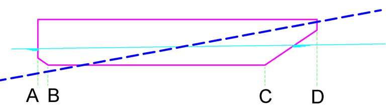
Side view of a pontoon.
Ratio of longitudinal frame distances
The distances between three successive points may not be smaller than 1:4, and not be larger than 4. If this condition is not met, the hullform can be saved anyway — it would be frustrating if that would be denied — however, each time when saving or reading the hull file a warning about this will be displayed. Take that warning at heart! If this condition is not met the accuracy of calculations might be impaired.
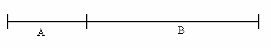
Frame distance ratio ¼ ≤ A/B ≤ 4.
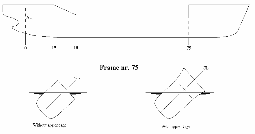
Double frames
As mentioned before, it is very important to define discontinuities in longitudinal direction by placing two frames on the same longitudinal position, (a double frame, two coinciding frames). The figure below gives an example of a ship with one discontinuity and two knuckles. This indicates we need three double frames at the positions 15, 18 and 75 metres from App. The two frames at 75 m are not alike to indicate a discontinuity there and the frames at 15 and 18 metres are alike to indicate a knuckle in the longitudinal direction.
Frame shapes.
Deckhouses as appendage
In general, the hullform is defined without superstructure. Deckhouses can be added later on with the option [appendages], see Appendages. In order to define a deckhouse properly, their fore side and aft side must be situated on a double frame. In order to achieve this, (identical) double frames have to be defined on forehand, at the locations where later on with [appendage] the extremes of the deckhouse(s) will be situated. [Appendage] will extend one of these frames with the deckhouse shape, and the other not.
A hole in the hullform
The position of a hole (such as a moonpool) has to be defined by placing a double frame at the aft and forward sides of the hole. In this case a double frame consists of one frame without the hole (the regular frame) and one frame at the same position including the hole, see the figure below. The frames in the hole area are defined according the example in the second figure. The points 1 to 6 define the frame. The height-coordinates of points 1,2,5 and 6 are equal but drawn differently for clarity. The water level in the hole always equals the outside water level.
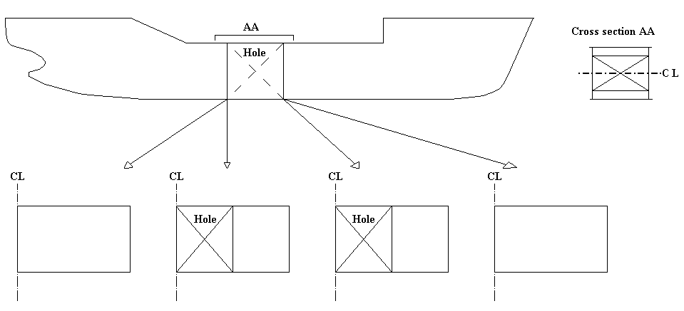
Hole at centerline.
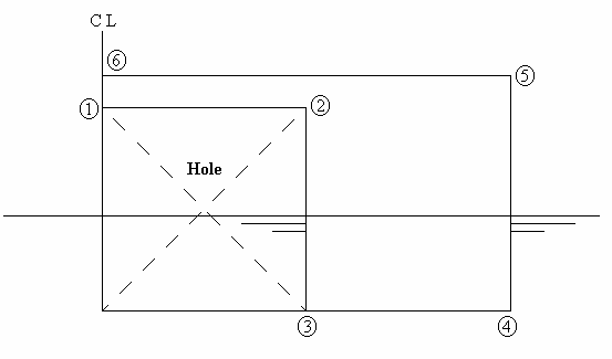
Frames in the hole region.
How to define the frame shape correctly
General tips are:
- The points of a frame should be defined in a counter-clockwise order (in the convention that the frame is situated at the right of centerline).
- The first point should be on the centreline. The last point on the deck in the side. Deck camber, deckhouses etc. are usually added afterwards as appendage, see Appendages, however, they can also simply be incorporated in the frame shape by a continuation of defined points beyond the deck at side, extending to centerline.
- A minimum of two points must be defined. As a rough guideline, twenty points will suffice to define a relatively simple frame correctly.
- The maximum number of points lies in the hundreds, however, the application of much more points than required to define the frame shape properly is discouraged. For the reason that the more frames are used, and the more points per frame, the longer subsequent computations will take.
- Frames with a tunnel do not need special treatment; simply follow the frame line counter-clock wise, regardless whether it is ascending or descending. This also applies to catamaran or trimaran types of hull shapes. See e.g. the figure just above, which illustrates how to define frames over a hole at center line, which is likewise applicable to a catamaran frame.
- Through ordinary (=non-knuckle) points a curved curve is drawn, at a knuckle a new curve starts. This notion ‘curved curve’ should be taken literally; if for example a point is defined twice, the frame curve crosses that point indeed twice, resulting in a nice loop in that area. And a triple point will give two loops. It might be evident that multiple, coinciding, points should be avoided!
- At a discontinuity of curvature in the line it is advised to apply a knuckle point, even if this point is no knuckle in the strict sense of the word.
- In regions of high curvature, it is advised to apply more points, where the curvature is low less points will suffice, in general.
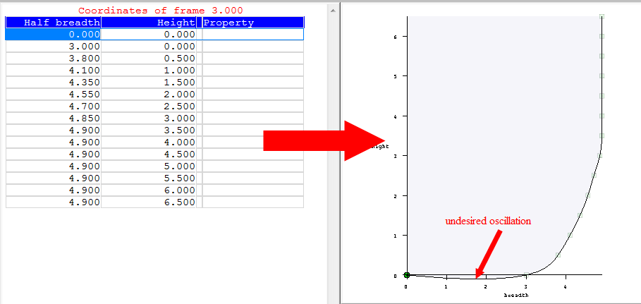
Unwanted undulation caused by too few points on baseline.
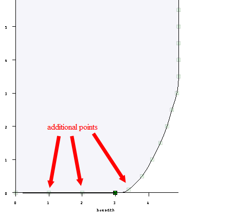
Proper curve shape with additional points on baseline.
In addition to these general rules, two pitfalls will be discussed here. The first one is the definition of a simple midship-like section, anyway, a section with a significant flat bottom part. If this is done by manually typing in the coordinates (re-typing a table of offsets) one might ‘naturally’ start with a point on baseline, followed by points on each subsequent waterline. In this case the effect might be that the frame will overshoot beneath the baseline, as illustrated in Unwanted undulation caused by too few points on baseline.. This can be prevented by inserting additional points on baseline, as depicted in Proper curve shape with additional points on baseline.. Alternatively, the point in the transition between bilge and baseline is defined as knuckle, in that case no additional points on baseline need to be given because the line between CL and bilge is between two knuckle and consequently strictly straight.
A second example is dedicated to the definition of the frame shape by digitizing. One might be inclined to tip a few points, more or less evenly distributed along the frame, however in this fashion regions of high curvature might be covered with too few points, leading to an unwanted undulation, as depicted in Unwanted undulations by too few points in region ofhigh curvature.". A solution is to digitize more points in highly curved regions, in our example the bilge area, although it is even better to apply two knuckles at the begin and at the end of this region. In that case the straight parts in bottom and side need no additional support, as illustrated in Proper curve shape by knuckles at both ends of the highlycurved region.".
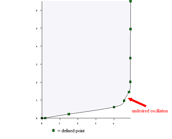
Unwanted undulations by too few points in region of high curvature.
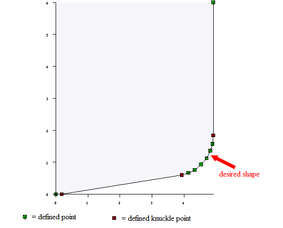
Proper curve shape by knuckles at both ends of the highly curved region.
Defining the shape of the frames
By placing the textcursor on a frame location, and pressing <Enter>, you reach the program part where the sectional shape (the shape of the frame) can be defined. For this task there are two alternatives, in the first place points on the frame can be defined by simply typing in their vertical and transverse coordinates and secondly a BMP file of the sections can be digitized from screen. Those two methods will be elaborated below.
Entering the breadth and height coordinates by keyboard
An input screen appears which displays two columns. The left column will contain the half breadth from centreline and the right column the height from the baseline. A fair curve will be determined through the given points, unless a point has been designated to be a knuckle, which can be done by placing the text cursor on that point and activating the [Knuckle] function. A knuckle is indicated in the coordinate table by the word ‘Knuckle’ after the coordinates. Ships are always fitted with an appendage (even if it is only a straight deck), at the starting point the word ‘Start appendage’ is displayed on the right; which indicates that the upper appendage begins at that point. The points of the appendage follow underneath and cannot be changed.
Defining the section shape by digitizing a BMP file
- Attention
- It happens regularly that there is no file available in BMP format, but in another graphic format, such as JPEG, PNG or PDF. This is not directly usable in PIAS, and will therefore have to be converted. Each tool can be used for this purpose, here are numerous viewers and converters that allow you to do so -—. e.g. with Windows Paint, XnConvert or XnView — googling on “Convert to BMP” results in 494.000 hits.
In the first place the BMP file) has to be selected by option [Window]→[Open]. Then the system of axes and the scale have to be set up, which can be done with this sequence:
- Digitize the origin, which is the intersection between base line and center line, with [Origin].
- Digitize a point on the baseline with [Baseline].
- Enter the breadth and height coordinates of a reference point with [Coordinates refpoint]). These coordinates are used to determine the scaling factors in breadth and height (which can differ, so there are two scaling factors). It is advised to choose a point as far as possible from the origin. The breadth of the scaling point must be given from CL, in general this breadth will equal half the ship's breadth. If the frames to be digitized are situated left of CL (as in general will be the case with the aft ship) then also a scaling point at the left side should be used, however, the given breadth coordinate should still be positive. When changing from frames left of CL to frames at the right (so, from aftship to foreship) a new scale should be defined. These coordinates are used to determine the scaling factors in breadth and height.
- Digitize this reference point, by option [Refpoint].
With these parameters the scale of the BMP drawing can be determined. In principle the scale should be the same for all directions, however, in practice it may happen that the scale in X-direction differs slightly from the Y-scale. That may have been caused when copying the body plan, where one direction is stretched a bit and the other not. Another source can lie in the scanner which may treat the two directions differently. Anyway, by means of these different scales PIAS will nicely correct such a distorted BMP file. In case of different scales an informative message will be given, similar to the picture below. It is advised to verify the scale differences; a small difference could have been caused by a stretched BMP picture. However, in case of a large difference, such as the 42% in the graph below, it is likely that the digitized points (which are used for the scale determination) are not correct.
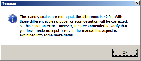
Information message on different scales in X and Y directions.
Modus operandi and options are further:
- Digitizing is performed by subsequently touching points on a frame with the cursor, and then pressing the left mouse button for each point of which the coordinates should be sampled.
- Digitizing a knuckle (at the intersection with a chine) is similar, except that first the function [Knuckle] must be activated. This function per knuckle, which implies that when digitizing three knuckles subsequently, this [Knuckle] function should be chosen three times. In that case it might be more convenient to indicate the knuckle with a double-click of the left mouse button, for that is another option.
- With [Markers] the colors and types of the markers (which indicate different kind of points, such as origin or knuckle) can be set.
- With [Re-digitize] all digitized points of the frame are deleted, and the digitizing process restarts.
- [Stop without save] and [Stop] are assumed to speak for themselves. They apply to the frame under consideration.
- With the function [Frames] the aft and forward boundary can be defined which will be used for drawing the already digitized frames. Might be convenient for the context, and to indicate the digitizing progress.
- The function listed above are included in the top function bar, however, they can also pop up in a floating menu by pressing the right mouse button.
- With key <Delete> or function [Delete point] the digitized point closest to the cursor will be deleted.
- With [Window] and [Arrange] other bitmap files can be opened (it can for example be convenient to have separate bitmapfiles of aftship and foreship both available) or closed, windows can be re-arranged etc.
- Finally, this window offers the facility to zoom with the mouse wheel, and to pan by pressing the middle mouse button (or the mouse wheel) while moving the mouse.
Appendages
This option enables you to define upper appendages, with a maximum of 30. The appendages are automatically added to the frames for the stability calculations, but do not form a fixed part of it. In the frame definition menu, the points of the hull form and the points of the appendages are visible, but only the points of the hull form can be changed. When the frames are printed, both the frame points and the points of the appendages, if the frame is within its boundaries, are printed.
Please be aware that an appendage, such as a deck house, can be the cause of a longitudinal discontinuity, in which case in the hull form definition a double frame will be justified, see Double frames for more details.
- Attention
- Appendages are always symmetrical around centerline. Asymmetrical appendages can be obtained with the asymmetrical hull form option, see Hullforms for more details.
When entering this appendage definition menu, a list of all present appendages is presented, which shows their most important properties. The possible action here is:
- [Remove from hullform] : In PIAS from before 2020, the points of the appendages were added to the specified frame points. If this is still the case with an old model, this option can be used to remove those appendage points. The defined appendages are then added to the shape of the ship in the new way. The appendages of such an old model can only be changed by first removing the appendages from the frame shape.
- By pressing <Enter> a new menu appears where all appendage particulars can be given, similar to the menu depicted below. In this menu the first line shows the type of appendage, and the second line the ‘description’, which is just a textual line for your own reference. The other lines depend on the type of appendage, of which five types are available:
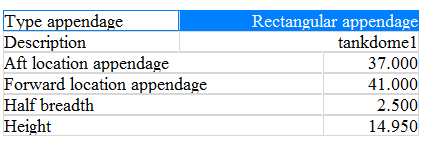
Appendage definition menu.
If no upper appendages are defined the vessel will be closed with a flat deck. For each appendage a few particulars have te be given, which are discussed below per type of appendage:
Deck camber
- Aft location of the camber. If the camber stretches itself over the entire vessel a large negative value, e.g. -100, should be given.
- Forward location of the camber. In case of a camber over the entire vessel, simply a large value should be given.
- The deck camber is given as divisor on the local breadth at deck, in other words as X for a deck camber of breadth/X. So for a camber of 1/50th of the vessel's breadth the value ‘50’ should be given.
Deck slope
- Aft location of the deck slope.
- Forward location of the deck slope.
- The deck slope is defined as X in deck slope=breadth/X, similar as with the deck camber.
Rectangular upper appendage
- Aft location of the appendage.
- Forward location of the appendage.
- Half breadth (from centerline) of the rectangle.
- Height (from base) of the rectangle.
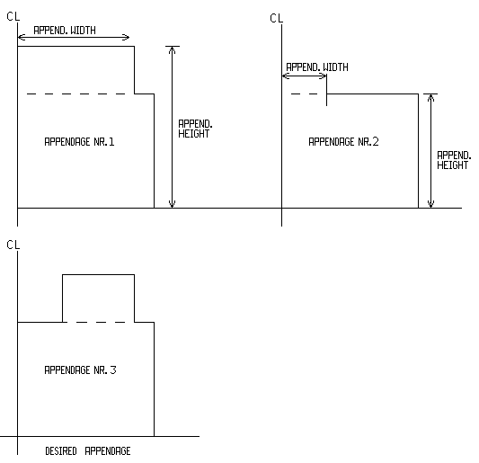
It is also possible to place two deckhouses on top of each other. For example, a deckhouse not extending beyond centerline can be defined as follows:
- First define the deckhouse over the entire breadth.
- Then define a deckhouse that is exactly the part to be removed with a height equal to the deck. See figure underneath. Appendage 1 is the deckhouse over the entire breadth. Appendage 2 is the appendage which defines the part to be removed. Appendage 3 is the resulting one.
Two deckhouses on top of each other.
Trapezoidal upper appendage
The trapezoidal upper appendage is similar to the rectangular type with the exception that the forward and aft locations can have different dimensions.
Upper appendage parallel to deck at side
This type of appendage is used to define a deckhouse with a constant distance to the deck at side.
- Aft location of the deckhouse.
- Forward location of the deckhouse.
- Distance from deck at side to the deckhouse.
- Height aft (from base).
- Height fore (from base).
Wind contour
With this option the shape of wind contours (=windage areas) can be given, with a maximum of twenty contours. The reason for defining multiple contours may be that a particular loading, such as container or a deck cargo of wood, might increase the windage area. For all those contours different wind moments can be computed, which e.g. also might lead to different values of maximum allowable VCG per wind contour. By the way, the Loading module offers specific submodules for specific types of cargo, such as for containers, where the actual loading is taken into account at the wind heeling moment computations. If this facility is used, there is no necessity to define standard contours for that cargo, here in Hulldef. Anyway, if the wind contour option is selected here, a menu similar as the one presented below appears:
The ‘selected’ column is only significant for the output of the contour in Hulldef. In subsequent computations, such as the maximum allowable VCG in intact or damaged condition, for which the stability regulations may contain a criterion for the effects of wind or weather, contours can be selected separately. The ‘in 3D view’ defines which of the contours is included in the three-dimensional view, at the right bottom window as well as on paper. In this menu two additional functions are available:
- [shifT], which facilitates in shifting a contour in length and/or height.
- [Merge], which facilitates in merging two contours. The selected contour will be merged with the copied contour.
- Attention
- This option is rather limited; the subcontours of the two merging contours are simply stacked after each other, and that is it. SARC also realizes that there are many ways to add 2 contours together, but they are not implemented here.
With the <Enter> key the program goes one level deeper, ‘into’ the list of subcontours, a menu similar as the one presented below appears:
For each subcontour a resistance coefficient can be specified that is used in the calculation of the wind moment. Overlapping subcontours are also double charged!
In this menu two additional functions are available:
- [Digit], in order to digitize a subcontour from bitmap file. This is analoguous to digitizing ordinates, for which reference is made to Defining the section shape by digitizing a BMP file.
- [shifT], which facilitates in shifting a subcontour in length and/or height.
With the <Enter> key the program goes one level deeper, ‘into’ the list of longitudinal and vertical coordinates of the subcontour. This list can be edited or extended. The complete contour should be defined including the underwater body. The last point should coincide with the first, so that a closed contour is defined.
In this menu the following function is available:
- [File], with which a subcontour can be exported or imported. The default name of the file is the name of the subcontour, but can be changed manually. The extension of the file is automatically ‘.sh’. The file format is as follows:
- The total number of points of the contour.
- Contour point column headings: ‘Distance ALL Distance base’
- And then of all the points the length and height coordinates.
Wind data sets
For an integral discussion on wind moments reference is made to Wind heeling moments.
With this option wind data can be specified, such as wind pressures. These particulars are not specifically linked to one contour, therefore they are given here ‘loosely’, so that for all combinations of contours and wind data sets computations can be made of wind heeling moments. First, at this option a list comes up which contains the available sets of wind data, up to a maximum of twelve:
The <Enter> key brings the user ‘into’ the set of wind data on which the text cursor rests at that moment, where the following menu is shown:
- Windlever must be calculated about, where the choices are half draft, C.O.G. of the underwater body and a fixed height. Commonly, the wind moment is calculated about the C.O.G. of the lateral area of the underwater body, however, occasionally it is required to calculate the wind moment about draft/2 or about some specific height (for example the centre of thrusters in a dynamic positioning system).
- If on the first line the type fixed height has been chosen, on the second line, at height whereabout the moments must be determined, that height can be given.
- At input/edit wind pressures the wind pressures (in kg/m2) up to a certain height above the waterline should be specified. The upper height of the highest wind pressure region should exceed above the topmost part of the contour. The safest way to achieve this is to specify a thousand meter as upper limit of the highest pressure region. The figure below gives an example of the use of two wind pressure regions, and it shows that the different wind pressure regions are indicated by different intensities of green.
- The goal of this [wind data] function in Hulldef is to specify the parameters for which the wind moment calculations can be executed. However, by exception the moments or levers may already be available from another source, for example from CFD simulations or wind tunnel experiments. In that case the wind levers (in meter) can be entered at the option user-defined wind heeling levers, where, after pressing the <Enter> key, an input menu appears where for each wind contour a table of heights/levers can be entered.
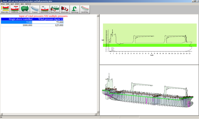
Two regions with different wind pressures.
Openings
An input window appears, containing a maximum of 255 special points, such as non-watertight openings, where the columns have the following usage:
- Name: an identification for this point.
- Length: the longitudinal distance from App of this point.
- Breadth: the transverse distance from centreline, where PS is negative and SB is positive.
- Height: the vertical distance from base.
- Type, which depicts the specific meaning of the point:
- Watertight: this is not an opening in the true sense of the word.
- Weathertight: this type of opening can withstand adverse weather, however, not permanent submersion.
- Margin line: a point of the margin line, which may play a role in damage stability regulations. Please consider that for accurate modelling many points of such a margin line should be defined.
- Open: a non-watertight opening.
- Point of a horizontal evacuation route: this type of point is applicable with probabilistic damage stability calculations, according to SOLAS 2009 & 2020, for passenger vessels. For details reference is made to reg. 7-2, par. 5.2.2 of chapter II-1 of SOLAS 2009 & 2020.
- Non-watertight opening (V-line): some naval stability criteria, notably DDS-079, apply the concept of V-lines, so when working with a PIAS version equipped with these criteria, a point can be declared to be of the ‘V-line type’. These V-line points are available in two variants, ‘non-watertight’ and ‘watertight door’. For the difference and background of these concepts in detail reference is made to the regulations from which they originate.
- Watertight door: some naval stability criteria, notably DDS-079, apply the concept of V-lines, so when working with a PIAS version equipped with these criteria, a point can be declared to be of the ‘V-line type’. These V-line points are available in two variants, ‘non-watertight’ and ‘watertight door’. For the difference and background of these concepts in detail reference is made to the regulations from which they originate.
- Emergency exit: see Types of parameters, Emergency exits to be included.
- Vertical escape hatch: this type of point is applicable with probabilistic damage stability calculations, according to SOLAS 2009 & 2020. For details reference is made to reg. 7-2, par. 5.3.1 of chapter II-1 of SOLAS 2009 & 2020.
- Buoyancy point: This point is used to calculate the freeboard to this point. The point with the smallest value then determines the 'Buoyancy index'. This index is used in some naval stability criteria.
Ventilation openings may be protected with so-called tank vent check valves (a.k.a. ventilation caps). The categorization (i.e. watertight, weathertight, open) of a particular type or brand of such a device depends on its construction, certification and interpretation of the particular authority. So, unfortunately, no general guidance can be given in this respect.
- Compartment: each opening can be connected to a compartment. In general, the rules for flooding of a vessel, when an opening is submerged, apply, however, if an opening is connected to an already flooded compartment it is, obviously, neglected. Openings connected to compartments can only be managed in Layout, (as discussed in List of openings and other special points) since they are part of their compartment. Such Layout-administered openings are also shown in this menu, however, in order to avoid inconsistencies they are not editable here — and are as indication of this nature printed in grey.
Furthermore, this menu contains two auxiliary functions:
- [+/-], which toggles the sign of the transverse coordinate (so the point switches from PS to SB or vv., does unfortunately not work for an entire selected column).
- [Sort], in order to sort the openings, which can be done in two sequences, either on type of opening, or on longitudinal position.
Deck line
For the calculation of intact and damage stability, and to verify against the intact or damage stability criteria, the program sometimes needs to know the deck line, which is by default not defined as such in PIAS. The first time this module is used on a ship, the deck line is derived from the hullform, at least, if a hullform model is available in conventional PIAS format. The deck line generated in this way could be erroneous, because it is assumed to be simple the connection line between the last points of all frames. Therefore, it is advised to check the deck line thoroughly. With this option it is possible to check or edit the coordinates of the deck line. A menu appears with longitudinal, transverse and vertical coordinates of the deck line. Besides the usual editing facilities, a couple of additional functions are available:
- [Derive] to (re)generate the deck line based on the PIAS frame model. Please realize that this may be an option to quickly derive the deck line from the hull shape, but it is certainly not a must to do it this way; after all, if that would be the case this action would have been automated. Nor is it at all necessary to give the deck line as many points as the ship has frames, e.g. for a ship with a curved hull shape and a rectangular deck without sheer or deck line jumps it is quite possible to define the ship shape with a hundred frames, and to define the deck line with only two points (i.e. aft and forward).
- [Switch side (PS/SB)] to toggle between the SB and PS deck line. With an asymmetrical vessel these could differ.
- [Mirror] to copy all points of the deck line from this side to the other, so from SB to PS, or from PS to SB.
- Attention
- The deck line, as defined here, only plays a role in the assessment against a number of (damage-) stability criteria. It has no effect on hydrostatics and stability etc. as such.
Output of hull geometry data
With this option all defined hull-related data can be outputted to printer or text editor file (e.g. to be imported into Word), with a preview to screen. Each option of the menu below produces specific output for a single data type, with the exception of wind data (as discussed in Wind data sets). Printing these wind data would be a bit overdone, because these data are already printed at the wind lever calculations where they are applied. The last option is not aimed at a specific data type, it can be used to produce combined output for multiple data types instead.
Main dimensions
This option prints a table which contains: main dimensions, added hullforms (as specified in Hullforms) and appendages.
Coordinates of all frames
With this option all defined points of all frames are printed. A K with a coordinate indicates this being a knuckle point. With this option the coordinates of the frames of other hullforms — from which the input is discussed in Hullforms and Extra bodies — can be included as well. If desired, this can be achieved by setting the ‘Print’ column to ‘yes’.
Two dimensional output of hullform
With this option several two-dimensional hull shape plots can be produced, such as:
- Body plan of foreship and aft ship, separately.
- Body plan of foreship and aft ship combined.
- A schematic lines plan. This ‘lines plan’ is rather schematic indeed, for example waterlines and buttocks are interpolated as good as possible, but because the sectional model of PIAS holds little information about the extremes of these longitudinal lines — which are not required at all for accurate computations — these extremes are omitted in the lines plan. Another simplification is configurations and colors are not configurable by the user. For a flexible definition and production of a high-quality linesplan the Fairway module is recommended, see Define and generate lines plan.
With the first sub-option of this option a number of plot parameters can be given. The first four (on frame numbering, upper appendages and the division between aftship and foreship) are applicable on all 2D plot variants, all other parameters, on waterlines and buttocks, are only applicable to the schematic linesplan.
Three dimensional output ship
Here the three dimensional output of all entities defined in Hulldef can be configured and produced. This output comes in two flavours:
- As lines model. This output is intended to be included in for example a stability booklet, and for that reason the output parameters are explicitly configurable here, and stored to produce exactly the same output format a next time — for example in case of a sister vessel or a design modification. The output parameters include:
- Whether the plot should be made including openings, deck line, wind contour etc. If set to ‘no’ then only the frame lines are included in the plot.
- The viewing direction of the ship. These are the viewing angles according to the convention of Definitions and units, which can, incidentally, be read at the bottom right in the window of the rendered model, as discussed just below.
- Whether the projection is in perspective, and, if so, the distance between the eye and the origin.
- As rendered model, please refer to the example and discussion of Rendered views.
Frame location table
This option prints a table of frame positions (in meter from APP), which contains the range between the aftmost and foremost frame, as specified at Frame spacings.
Combined output
With the other options of this menu individual data types can be printed. However, it might be handy if multiple data types can be specified, and printed in a single action. In particular, in case of a design change the whole bunch of data can be printed with a single command, without bothering about the output sequence and chapter numbers. This background is the reason of existence of this option, which allows in multiple rows to specify the data type chapter name and page number. With menu option [Print] the output in actually produced.
Export of hull shape data to a number of specific file formats
With this option the frames, as defined in PIAS, can be exported. In this respect one should realize that the exported data is in principle limited to the available data, which are, in PIAS, frames. with an accuracy (more than) sufficient to perform naval architectural computations. However, they do not necessarily on construction tolerances. Earlier PIAS versions, from the 1980s and 1990s, also contained frame conversion facilities to CAD software such as Autocad, however these functions have been scrapped with the rise of Fairway, which allows a far more accurate and above all more complete (e.g. including waterlines, stem and stern contours and surface models) definition and export. For this reason, the export from the Hulldef hull form is now limited to:
- PIAS-standard ASCII text file of sections, from the format as described in The "PIAS standard" text file format.
- Poseidon, a DNV•GL rules program. PIAS also contains an option to export the internal geometry to Poeison, more information on that can be found in Export to Poseidon (DNV•GL).
- Castor, the steel weight estimation program by ASC.
- Frames to Eagle, as in use by Conoship.
- Frames to Fredyn, Shipmo and Precal, for ship motion analyses, from MARIN, www.marin.nl. The Shipmo conversion is aimed at 2006-2016 Shipmo versions.
- Wireframe model to Fredyn. Fredyn imports two representations, the first is a frame (sectional) model, as generated with the previous export option. The second is a wireframe model, from this particular option. The wireframe is more complete (because additional longotudinal connections are constructed), however, the hullform should satisfy a number of constraints in order to be able to use this function.
- Seaway, a ship motion program by Amarcon, www.amarcon.com.
Import frames from (a number of specific formats of) a text file
With this option cross sections (ordinates) from a text file (ASCII file) can be converted to PIAS format. On this process the following comments can be made:
- The recommended definition method is through the modules Hulldef (for existing body plans) and Fairway (for new designs). Nevertheless, this facility might prove to be rather useful for importing body plans from another source.
- Here, no CAD files can be imported here. Such an option — notably from DXF and IGES formats — is indeed available in PIAS, however, located in the Fairway module (see The entire procedure to import DXF or IGES files).
- This conversion routine does not perform any validity check. So the user should verify that the information in the input file is complete and correct, on two levels:
- Syntactically, which means that the numbers in the text file have the correct format (such as a decimal point instead of a comma) and are placed on the right position in the file.
- On content. The definition of a PIAS hullform must comply to a number of requirements, which are listed in Frames (frame positions and frame shapes), such as the frame order (from aft to fore), the maximum number of cross sections and the maximum number of coordinates foreach cross section, the sectional distance ratio and possibly the ‘double frame’ requirement.
After starting the import function, a short input menu with 4 options appears:
- Import file name. The file name as specified here is not retained. That is deemed unnecessary because, as a rule, an import action will only be undertaken once per project.
- File format import file. Only the formats ‘PIAS standard’ and ‘XML’ are actively supported. The other formats have once been developed for specific users or applications, however, they are not documented — anyway, not in the context of PIAS.
- Hullform type. Here you can select what kind of hullform should be added; a symmetrical main hullform, added hullform, etc.
- Import as polylines. If this option is set to ‘yes’, the frames are imported as polylines (= chain of straight line segments between frame points) and cannot be modified in PIAS. However, the shape can be used for further definition and calculations. The advantage of the polyline is that its number of points per frame is unlimited, whereas in the standard way a limitation applies (incidentally, in general to more than 100 points per frame, so not that tight). The [Import] function actually reads the file and adds it to the list of shapes set at hullform type (one line higher in this menu).
The "PIAS standard" text file format
A file of this format essentially consists of a number of cross sections, with for each cross section a number of points on the hull surface for that cross section. So, this information is completely equivalent to that as is defined with Hulldef. The file should have this content:
- Number of cross sections (frames).
- For each cross section:
- Location from Aft Perpendicular (APP).
- Number of coordinate pairs.
- For each coordinate pair the breadth and height of this coordinate, and a 1 if this coordinate is a knuckle, or a 0 to indicate a smooth curve through this point.
An ‘PIAS standard’ file for a rectangular barge with main dimensions 100 x 20 x 10 m, with two cross sections will for example have the following content:
| 2 | | |
| 0.000 | | |
| 3 | | |
| 0.000 | 0.000 | 0 |
| 10.000 | 0.000 | 1 |
| 10.000 | 10.000 | 0 |
| 100.000 | | |
| 3 | | |
| 0.000 | 0.000 | 0 |
| 10.000 | 0.000 | 1 |
| 10.000 | 10.000 | 0 |
Generate cylindrical shapes
With this option cylindrical shapes, notably a longitudinal gas tank with a more or less circular sectional shape, can be defined parametrically, and converted into a PIAS sectional representation. The main cylinder parameter is its orientation: longitudinal, transverse or vertical. For a longitudinal cylinder the other parameters are:
- Outer radius, the cylinder radius.
- Cylinder extremities: the aft and forward location.
- Cylinder axis above base: height of the center of the cylinder above baseline.
- Cylinder axis from CL: the transverse distance of the center of the cylinder from center line.
- Type of tank head aft and forward, for which three types are available:
- Circle head.
- Korbogen head (R= 0.8 D).
- Deep dish head (R= 0.714 D).
- File name of PIAS frames: name (and path) of the PIAS hull shape file name.
For transverse and vertical cylinders, the parameters are similar, with the exceptions that these types can be hollow, while the specific types of tank heads are not applicable to these types. With the defined parameters a hull shape in standard PIAS sectional representation can be generated, which can e.g. be applied as ‘external compartment shape’ at the compartment definition module Layout. Below an example of such a representation is depicted.
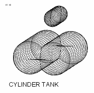
Cylindrical tanks.
File and backup management
Backups of the hull-related data can be made and restored here. Here is also the option ‘Stop without saving’. See for the details Data storage and backups.
- Attention
- These file and backup management options are applicable to data as administrated under the current project and which are consequently saved under the project file name. However, other hullforms or bodies, as discussed in Hullforms en Extra bodies, are essentially independent projects with its own file name. These are consequently not included in this file and backup management system.
Rendered views
In a number of places in PIAS a system is used where the three dimensional shape of curves and/or surfaces is plotted in a rendered fashion, which means that hidden surfaces are not shown, that lighting can be applied etc. This option is here in Hulldef available with the output, please see Three dimensional output ship, but is also used other modules, particularly in Layout and Fairway. For that reason, the options of this system is discussed here in a separate section. From the rendered view in Hulldef an example is depicted below, which shows section curves, openings, deck line etc., exactly those elements which have been specified to be included in plots with option [View] of the input menu of this module, see Input, edit and view general particulars and hull geometry data.
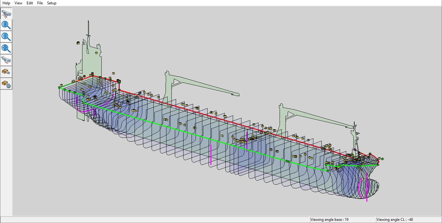
Three-dimensional, rendered, output.
At the left side in each three-dimensional subwindow is a number of buttons that are specifically related to that subwindow:
- Rotate: assigns the rotation function to the right mouse button. This is the standard.
- Zoom+ and Zoom-: zoom in and out. It is also possible to zoom dynamically with the mouse wheel.
- Extend: zoom to full-screen.
- Pan: assigns the dragging function to the right mouse button. By pressing the mouse wheel button permanently one can also drag without using this function.
- Clip: one can clip the 3D subwindow i.e. that one can define a hexagonal box, where only the contents of that box is visible. With this clip function one switches the clipping on and off.
- Setclip: six clip boundaries can be set with this function. When this function is active, the hexagonal box appears, a bit transparent, and by standing on one side and by pressing the right mouse button permanently one can drag that side.
Actually, these buttons are shortcuts to functions of the upper menu bar, which will be discussed in the next paragraphs. By the way, not every render window is equipped with those lefthand buttons, because in some occasions functions have been left out because of irrelevance in the context of that module. However, if the functions are present they always act the same.
View
Most of the functions here, such as zoom and rotate, have been discussed right before. Additionally, this [View] menu contains an option [(In)Visible] which can be used to make certain parts visible or invisible, but that will speak for itself. More can be said about the dedicated function [Orientation box], which finds its background in the fact that although for a rendered view a viewing direction can be chosen, an orthographic (= non-perspective) projection of a lines model can be ambiguous; the viewing direction has been set; however, it is not evident from which side of the viewing axis the object is viewed. So, such a projection can always be seen from two directions, somewhat similar to the ‘optical illusion’ which can include totally different images into one picture, as illustrated with a well-known example below.

Optical illusion: young or old woman?
Although this is a principal phenomenon, PIAS has two tools which may assist in finding the right orientation. In the first place the viewing angles are often shown, according to the convention of Definitions and units. And secondly, the orientation box can be switched on, which gives a PS part of the object a red envelop, and the SB part a green envelop. The top and side planes are transparent, but the bottom plane is opaque, so if this plane covers a part of the object it will be clear that the viewing direction is from below.
These tools do not guarantee a correct mental image of the picture — the viewer should also be prepared to set his mind's eye properly — but experience has learned that they are a good aid.
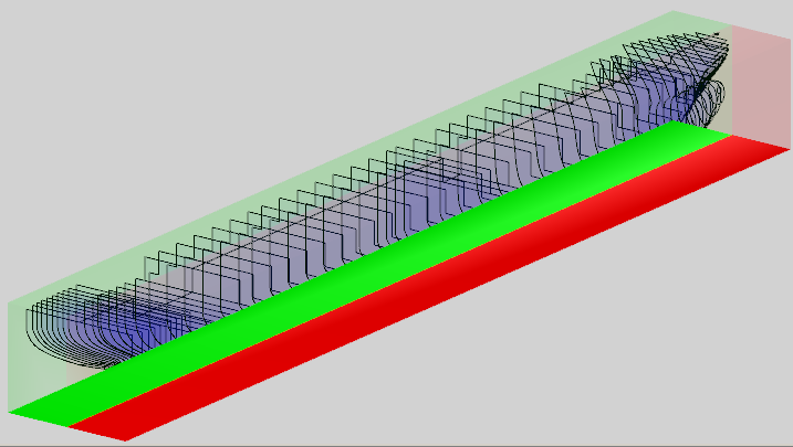
Orientation box.
Edit
With this function the position and intensity of external light sources can be set. One can also change the colors (as well as reflection characteristics and transparency); when the mouse pointer is standing on a part of a ship then its color can be adjusted; when the pointer is standing on nothing at all, then the background color is adjusted.
File
Save image in file
With this option the screen image will (two dimensionally) be saved in bitmap format. here a reduction factor can be given from which the background is discussed in Print image.
Copy to clipboard
With this option a copy of the image is made to Windows' clipboard, which can subsequently be pasted into documents of other applications.
Print image
After the selection of this option an input box pops up, where a reduction factor can be given. This is a bit of a technical parameter, which had to be included. For, when a printer is configured to print at a high resolution, a very dense picture will be produced. The file size of these pictures can be fairly large, which should pose no problems as such, however the sad experience has learned that Windows is not always able to cope, which may lead to a program crash. The use of this reduction factor reduces the picture size as well as the probability of failure significantly.
Generate VRML file
In a VRML (Virtual Reality Modelling Language)-file a 3D representation of the model is captured. This representation can be visualized using a VRML-viewer. Various VRML-viewers are available as shareware on the Internet. The options [File]→[Generate VRML 1.0 file] and [File]→[Generate VRML97 file] respectively produce a file according to the original VRML 1.0 specification, and the more recent, and more popular, VRML97 format.
Setup
Select Nearest
With this option on, while selecting an object always the thing closest to the eye (of the viewer) is taken. However, occasionally a deeper object might be intended to be selected. With this setting off a list pops up containing all objects on the cursor location (regardless of their depth) from which the user can chose.
Auto apply
Some options from the [Edit] menu have an [Apply] button, which will make modified visualisation settings to be processed. However, when [Setup]→[Auto apply] is set, each modification will immediately be processed. This gives a much more responsive character, however, at rare occasions a computer may be too slow for auto apply