List of openings and other special points
From each compartment its openings and other special points can be given, as discussed in Special points / openings (to which we also refer for the purpose of the input cells). However, it may be convenient to collect all special points in a single list, which is performed by this option, on which the following remarks can be made:
- The order of points in this list is primarily that of the compartments. The order can be changed, for example by inserting points, or by [Sort], however, such a new order will only be temporarily. In the end the compartment order still prevails.
- [+/-], the sign of the transverse coordinate will be toggled (so the point switches from PS to SB or vv., does unfortunately not work for an entire selected column).
- With the [Sort] option points can be sorted in the order of the content of the column where the text cursor resides. Also this order is temporarily.
- Compartment openings, which are defined here, are also visible in Hulldef, please refer to Openings for a discussion. That Hulldef list may also contain other points, such as those of the margin line, which are not relevant here. However, it may also conntain openings which are not connected to a compartment, and although such points play also no role here in Layout, as a service they are still included in the list of this menu option. Their compartment indication is ‘–Not from a specific compartment’. Because their relevance is less than that of ‘real’ compartment openings, their place in the list is at the bottom (while in Hulldef they are listed at the top, that is not a matter of sloppiness, the reason is that the focus is just different). This type of openings will only be stored in Hulldef format if the setting “Always create conventional PIAS compartment files at save” (please see Layout project settings and function colors is switched on.
List of physical planes
Here a list appears of physical planes, with nine columns, namely:
- Name and second name: the two names of the plane. Similar as with compartments, it can be set that the second name should be generated automatically, with the setting discussed in Layout project settings and function colors.
- Abbreviation, of eight characters at maximum.
- Abs.position: the position of the plane, in metres from App, CL or baseline. For an angled plane also a position is presented, which is — similar to orthogonal planes — the perpendicular distance between this plane and the origin, where the sign (+ or -) is not relevant. This position — not just as fixed by this column, but also by the next column — can be constrained by the presence of other planes, as explained in Limited positioning of a physical plane.
- Rel.position: the position of the plane in relation to a reference plane, at least, when the plane has been relatively defined.
- Orientation: longitudinal plane, transverse plane, horizontal plane or angled plane.
- The plate thickness of the bulkhead or deck (in meters!).
- The specific weight, which is the weight/m2. If the plane thickness is filled in, and the weight/m2 is still zero, then the latter is adjusted according to this thickness, for shipbuilding steel. However, this is a gadget, because in reality stiffeners and girders will probably increase the specific weight (note: when exporting to Poseidon (see Export to Poseidon (DNV•GL)) structural elements can be defined, and that information could be used to determine the specific weight here including that structure. If you are interested in such a feature you can contact SARC).
- Position is not modifiable by Constraint Management: whether this plane will maintain its location if Constraint Management is going to modify the plane positions.
- Number of constraints: here the amount of constraint that apply to this physical plane can be inputted. Then per constraint the correct constaint can be selected from the constraint table via a popup-menu.
In the menu bar of this list is, apart from the usual menu options, a number of specific options:
- When adding a new plane, one directly enters the popup menu of Popup menu for geometry of points or planes.
- [Geometry], with which one can change the shape of the plane. Directions are described at The shape of a plane (the green dots).
- [Sort], with which one can sort the planes by columns, i.e. in the order of the data of the column where the text cursor is. This sorting can also be undone again with [Undo].
- [Area tAbles], which will produce a table containing the area and Centre of Gravity for each plane. If also specific weights are given for all planes, then the totalized weight and CoG of the internal ship's planes are included as well. The weight of the shell plates is not included here, but can be calculated using the shell plate expansion function of Fairway, see Shell plate expansions and templates.
In all but the sixth column one can enter values directly. With <Enter> one enters a popup menu with all data of the plane, and when one at the absolute or relative position presses on <Enter>, one enters the plane definition menu that is described below.
List of reference planes
This list contains all reference planes, and is concerning operation and content similar to the list of phisical planes, just above. However, there is an additional rightmost column which lists how often a reference plane is actually used. When entering such a cell a popup window appears with this information split out in compartments, reference planes and physical planes. On this info two remarks can be made:
- The summation counts all parts which can be related to a reference plane, so not only the measurements of compartments and planes, but also those of sounding pipes and openings etc.
- Although the subcompartment shape might externally be of different types (such as ‘simple block’ and ‘four longitudinal ribs’, seee Types of subcompartments "with coordinates"), internally it is always stored by means of its corners. This implies that certain shape definition measurements may be counted more than once. for instance if an aft compartment boundary has four corners, and that aft boundary is defined by means of a reference plane, it will be inlcuded four times in the reference plane count. Nothing to worry about, but it is good te be informed on this phenomenon.
So, in this menu reference planes can be defined. Letting points and other planes refer to a reference plane is discussed in Popup menu for geometry of points or planes. Apropos, a reference plane can be defined relative to another reference plane, etc.
Compartment tree
With this option there appears a popup box with the same compartment tree view as used in the GUI. Essentially, this tree contains no more information than the regular compartment list of Compartment list, calculation and printing of tank tables, except for that it is shown here per compartiments and subcompartiments in one overview.
Layout project settings and function colors
Project settings.
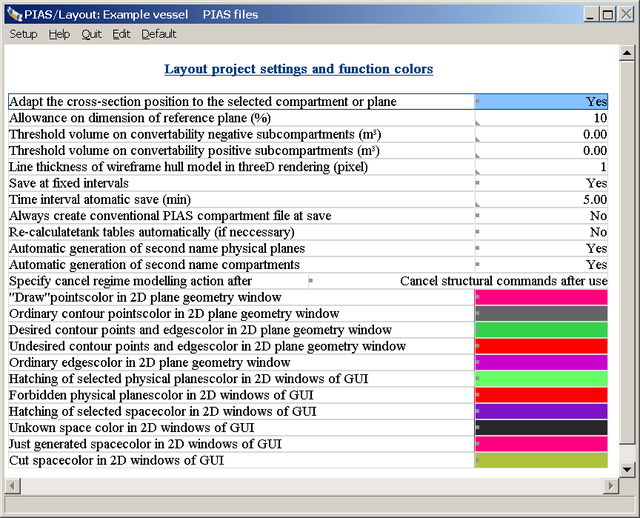
With this option appears the above popup screen, in which a number of program features and colors can be set:
- The cross-section position of the three orthogonal cross-sections is controlled anyway by clicking in such a cross-section on the right mouse button, then the position of the other cross-section is equalled to the position of the cursor at that moment. But apart from this mechanism, one may also opt for adjusting that cross-section position to a plane or compartment that has been chosen in the compartment tree or planes list. If you want this, then you have the put the first option on yes.
- Allowance: It is useful when the reference planes are drawn slightly larger than the rest of the ship. That extra size, the allowance, can be defined here.
- Threshold volume: at a conversion of a compartment configuration to a plane configuration, negative subcompartments can be included integrally. This may result, however, in a substantial increase in the number of used planes, which is not necessarily desired. That's why one can define a limit value (of volume, in cubic meters) here under which negative subcompartments are not included in the conversion to planes, they still exist of course, but simply as subcompartment of the type ‘with coordinates’.
- Line thickness will be obvious.
- At the time interval one can define per how many minutes the model is saved automatically. That can be useful in the event of failures, then you still have at least a recent model.
- Automatic generation of the second name of physical planes or compartments. Compartments and planes have, obviously, a name. For additional identification also a second name may be given. For enhanced convenience, with these two options in wuestion it can be set that these second names are generated automatically, based on the location of the object, according to these systems:
- Physical planes get a plane type, and their position. If frame spacings have been set (as discussed in Frame spacings) then longitudinal positions are not given in meters, but in frame numbers (with possible an offset in mm) instead.
- Compartments get a combination of aft boundary, forward boundary, side (PS, SB or ‘over CL’) and the weight group as assigned to this compartment.
This mechanism permanently updates these second names, so existing manually entered names will be overwritten.
- With option [re-calculate tank tables automatically] the tank tables are (re-)calculated whenever neccessary, that is when the compartment geometry is jounger than the available table. This automatism may take some time, however, for the benefit of table consistency.
- For the cancel regime see How long stays a function assigned to a mouse button?.
- The colors will be obvious. The color of ‘rdesired contour points’ is for that of the ‘green dots’. The ‘just generated space color’ and the ‘cut space color’ are only used at a compartment color schedule ‘uniform’ (see for that View). The ‘draw’points color is as used with the draw function in the GUI, see Draw.
Names and color per part category
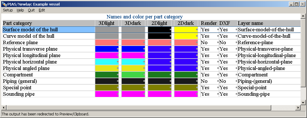
Names, colors and other part properties.
Herewith one can choose the colors of the various ship's items. In Layout project settings and function colors one could also configurate colors, but that was meant for program items, here we are talking about ship's items, of which seven features can be defined:
- The first column contains the identification name of a category. This is mentioned here for the purpose of recognition, and cannot be changed anymore.
- In the next two columns one can set the color as it is used in the 3D views, in the second column for a light background, and in the third column for a dark one.
- Subsequently two columns in which one can set the color as it is used in the 2D cross-sections (the orthogonal cross-sections), also for light and dark backgrounds.
- In the sixth column one can define whether this category must be included in the output of the 3D render model, the production of which is described in Threedimensional presentation.
- In the seventh column one defines whether this category must be included in the DXF output of the general arrangement plan, the production of which is described in 3D-plan to DXF file.
- In the eighth column one can define the layer name that is allocated to this category in such a DXF output. When defining the layer name one has to observe the conventions of Autocad, or another recipient CAD system. Thus a layer name can have, for example, a specific maximum length, or some signs may be forbidden. For the exact nature of these restrictions, you will have to consult the documentation of the recipient system.
The color of a ‘piping system’ is just the default, which is assigned to a new system. If desired, for each individual system an andividual color can be assigned, see Pipe lines and piping systems. The display of container positions in the layout was temporarily abolished in 2021, as PIAS was provided with a completely new container module at that time. Upon completion of the container part of Cargoquip, this will be reactivated.
Define weight groups
With this option one enters a menu where features of weight groups can be defined. A weight group is a specific category of weight, of, for example, a ship or cargo. At the definition of compartments can be defined at the compartment what the weight group is of the volume for which this compartment is intended, for example potable water or palm oil. Color combination or output of loading conditions can take place per weight group. This menu is discussed in more detail in Weight groups.
Notes and remarks
With this option an input screen appears with which one can make separate notes. These notes are saved at the subdivision plan, and can always be altered later on.