A list of compartments turns up here, with several columns — for which the order can be set by the user, see Input window — which are explained in Compartment data.
The upper bar contains some specific functions:
- [Manage], with the following sub-options:
- [Copy] and [Paste] will speak for itself. One might wonder why these options are not included in the general copy/paste under [Edit], as common in PIAS. The reason is that over here also a [Paste Link] option exists, which is not facilitated in the regular [Edit]. In this respect Layout is an exception. Perhaps u.nnecessarily: the [Edit] options — as discussed in Copy, paste etc. — only exert on the visual cell values, which can e.g. be exchanged with a spreadsheet, while the copy/paste here under [Manage] concern all compartment data, including all underlying subcompartments.
If the compartment contains subcompartments of the type ‘Space generated between planes’, at pasting, these are converted into type ‘with coordinates’. This is inevitable, because the space between the planes exists once and cannot be duplicated. If this conversion is not possible (e.g. because the compartment shape cannot be represented with only coordinates aft and forward) then that subcompartment will be excluded from the copy.
- [Paste Link], see the explanation at Subcompartment functions.
- [Move], which can be used to move a compartiment up or down in the compartment list.
- [Sort], herewith the compartments can be sorted according to column (i.e. in the order of the data of the column on which the text cursor is standing), to position and to time of definition. The selection can be undone again with [Undo last sort].
- [tAnk tAbles], with which one can calculate and print tank tables, see Calculate and print tank tables.
- A row of icons, which may be used to invoke some of the other upper bar manu functions. These icons are presumed to be self-explanatory, although additional assistance is given by hovering over the picture. When one has entered into a tank table, by means of <Enter> in the rightmost column, these icons are also present although they will obviously not be functioning here.
With <Enter> in any other column one enters the compartment definition screen, which will be discussed later on.
Compartment definition window
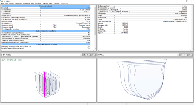
Compartment definition window.
Design of the compartment definition window
The compartment definition window consists of the following items:
- Top left a list of compartment characteristics, such as name or sounding pipe data. These are explained in detail in Compartment data.
- Bottom left a 3D view of the compartment. In this window one can call up a number of functions with the right mouse button as they have been discussed at Operation in the 3D subwindows. By the way, mouse wheel is zooming in-out.
- Left of centre an drop-down list of compartments, from which one can choose another compartment (one can also type a name here, but nothing happens then). Choosing the previous and next compartment can also be done with the two buttons at the right of this list.
- At the right three subscreens related to subcompartments, and which have the same purpose as the three subwindows discussed above.
- At the bottom a status row, with explanations and/or sizes related to the cell where the text cursor is standing on.
Changing between compartments and subcompartments can be done through indication with the mouse pointer, but also with the <Tab> key. Subsequently, there is still a number of functions to be called up in the upper bar, which are discussed below. The upper bar also consists of the + and - functions, with which one can jump to the next or previous compartment (when the text cursor is standing on the left window) or subcompartment (when the textcursor is standing on the right window). These functions have been included so one can quickly go through the (sub)compartments with <Alt><+> and <Alt><->.
Reference planes can be used for all coordinates of compartments and subcompartments, so not only for the compartment boundaries but for example also for openings or the sounding pipe. A reference plan ecan be selected by pressing <F5> in that particular cell. This activates a popup window that is further discussed in Popup menu for geometry of points or planes.
- Attention
- Copy/paste functions, as discussed in Copy, paste etc., are not implemented here. These input windows have such a variable structure that this will hardly fit.
Types of subcompartments "with coordinates"
A subcompartment of the type ‘with coordinates’ is always defined with an aft and a forward boundary, and in each of it a number of points which represent the horizontal and vertical subcompartment boundary. In general, this is a flexible definition, enabling considerable freedom of shape, but since the major part of the subcompartments does not need this flexibility, a number of subtypes has been defined in order to increase userfriendliness:
- Simple block
- A ‘simple block’ is a limited interpretation of the general subcompartment definition, namely with straight horizontal and vertical boundaries. This type can be recorded with six numbers (aft, fore, inside, outside, upper and bottom).
- With four longitudinal ribs
- This is a slightly extended interpretation, where the number of ribs N=4, but where the longitudinal boundaries are not limited to purely horizontal or vertical.
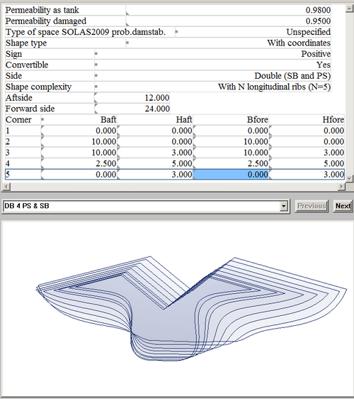
- With N longitudinal ribs
- This type is even more extensive, so three-sided, five-sided or multilateral subcompartments can be defined with this setting. Note that the direction of rotation according to the vertex order must be left turning (counter clockwise). The number of longitudinal ribs ‘N ’can be given via [cOordinates]. An example of what the subcompartment definition screen contains for a five-sided compartment is shown below:
- Attention
- As coordinate also ∞ can be entered, in which case the outer hull is taken as subcompartment boundary. That is quite handy, however, please realize that such an ∞ should be used for (the corresponding coordinate of) both aft boundary and forward boundary. The reason is that interpolation between finite and infinite is undefined. With such invalid input the program prints the warning ‘corresponding coordinates of aft and forward boundary should both be finite or infinite’, and leaves it to the user to correct the input coordinates.
Compartment functions
Adding and removing will be obvious; With [Insert] a compartment is added that is included in the list of compartments before the present compartment, and with [New] after it. [Copy] copies the compartment data, including all subcompartments to an internal clipboard. With [Paste] the compartment data, including all subcompartments, are copied from that internal clipboard to the present compartment. All existing compartment data (including subcompartments) are transcribed thereby. The difference between [Paste] and [Paste Link] is explained in the following paragraph.
Subcompartment functions
The functions [Insert] through [Remove] are entirely analogous to those discussed at the compartments, we refer to the previous paragraph. The [Paste Link] is related to references of subcompartments, as explained in Links to subcompartments. With [Paste] the subcompartment data are copied to the present compartment, with [Paste Link] a reference is made from this subcompartment to the shape of the copied subcompartment.
Coordinates functions
These functions are related to a subcompartment of the type ‘with coordinates’. With subtype ‘other than four longitudinal ribs’, as discussed in Types of subcompartments "with coordinates", there should be a facility to add or remove rows, in order to change the number of ribs. The first three functions ([Insertrow], [Newrow] and [removerow]) are meant for that. Because most subcompartments are prismatic (i.e. that the aft and front boundaries have the same shape), for practical purposes there is a [Copyaft] function, which will copy all coordinates from the aft boundary to the forward boundary. This function is also relevant for type ‘four longitudinal ribs’
View functions
Without a special setting, all subcompartments of a compartment are drawn interchangeably in the left bottom subwindow, irrespective whether they are positive or negative. Mutual connections of two (positive) compartments are drawn then, although one could argue that they do not exist in a physical sense, and could therefore be omitted. With the [visually composed] function active subcompartments are actually composed graphically, so that they render a more realistic image.
- Attention
- At this ‘visually composing’ of subcompartments, these are neatly cut off when they overlap. The shape of negative subcompartments is also deducted from those of the positive ones. This offers a good insight, but do remember that the calculation is based on the ‘bare’ subcompartment shape, so overlappings are calculated double, and a too large negative subcompartment may result in a negative compartment volume.
When the [Surfacemodel] function has been activeated, the (sub)compartments are not drawn as frame model, but as surface model instead. All this on the condition that either a surface model of the hull is available (see Hull form representations) or the (sub)compartment is not at all cut through the hull. If one visualizes a (sub)compartment with a surface in this manner, one can also switch on the [Transparent] function, with which the surfaces become partially transparent, so that also the sounding pipe remains visible. That renders such images:
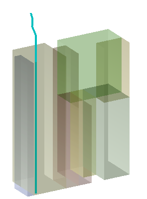
Semi-transparent compartment with sounding pipe.
Tank tables
This menu bar option only contains one option, [Calculate], for calculating the tank tables of the current compartment. For further information see Calculate: compute the tank tables.
Compartment data
Selected
Indicates whether this compartment has been selected for further actions, such as calculations and output.
Compartment
The (unique) name of the compartment. Although fifty characters have been reserved for the names in Layout, the input here is for the time being limited to 28, for the reason that this 28 still is the maximum in subsequent modules, such as Loading. When also those modules have been upgraded to the higher maximum, the input limitation will be removed.
Second name and abbreviation
These are supportive names that can be included in some output for cosmetic or explanational purposes. For example, the second name at tank tables, and the abbreviation, of maximally eight characters, at the tank plan (since too long names will soon mix up there through several tanks). One can also choose to have this second name generated permanently, please refer for that to the settings as discussed in Layout project settings and function colors.
Design weight group
Indicates to which weight group the volume of the compartment belongs. This value is used as default in loading conditions. If such a value is not known or desired, one may also opt for ‘undefined’. The purpose of weight groups and its defining has been discussed in Define weight groups.
Uniform permeabilities
Permeabilities can be defined here for all subcompartments in one action. See Permeabilities for further merits.
Design density
Here the density (specific weight, in ton/m3) of the liquid for which this tank is intended can be given. This value is used as default in loading conditions. If such a value is not known or desired, one may also opt for ‘not specified’, then there is no default.
Uniform subcompartment sides
One action can record the side for all subcompartments here, see Side for the options.
Sounding pipe
Two sounding pipes per compartment can be defined. Each of them takes up one row, where can be defined:
- The name of the pipe. This is initially a default name, depending on the selected output language at the moment the compartment is created, but these names can be changed manually.
- With ‘selected/deselected’ in the right column one indicates whether this pipe has been selected for output, such as drawings and tank sounding tables. Besides being selected each pipe also belongs to an exclusive category (‘A’ to ‘J’), which enables the output script to identify the desired sounding pipes in the sounding tables (see Output scripts for details).
- With [enter] a window pops up in which one can define the coordinates of the pipe, which can also be referred (via <F5>) to the reference planes, a feature that might be useful in the event of future design modifications. The maximum number of coordinates is fifty, so that also curved pipes can be properly modelled. Furthermore, for verification purposes in the status line, right-under in the window, the total pipe length is represented. Finally, this window als has a [Selected] function which does exactly the same as the ‘selected/deselected’ of the previous line. As the rule a pipe will consist of two or more points, however, it is also possible to define a “pipe” with only a single point. Its effect will be discussed in Output scripts.
Special points / openings
Characteristics can be defined here of specific items that belong to the compartment. There are several predefined types of such items:
- Open opening
- This is an open opening to the outside, which is connected with the compartment, for example, an unprotected vent.
- Weathertight opening
- An opening to the outside which is connected with this compartment and protected such that it can be considered to be weathertight. Some authorities consider a vent cap to be sufficient protection to that end, others not.
- Watertight ‘opening’
- Obviously, this type has no effect. it is included for convenience, for example to be able to toggle an opening ‘off’, or to indicate that one has not forgotten or ignored a closable opening, but that it really securely closed.
- Emergency exit
- See Types of parameters, Emergency exits to be included.
- Hopper edge or overflow
- Are solely intended for open hopper compartments, from which cargo can pour out. Their details are discussed in Specify additional hopper properties.
- Alarm sensor
- In order to be able to process its effect in tank tables and maximum tank filling.
- Pressure gauge
- Its location is important for the calculation of pressure tables (i.e. the tables that indicate which tank filling belongs to a specific sensor pressure), and in order to be able to determine the corresponding volume at loading conditions and/or loading software at a known sensor pressure.
At [enter] a window pops up in which can be defined:
- Whether the point has been selected is defined in the last column. Only selected points result in an action. When a point has not been selected, it is just as if it does not exist at all. So selection is intended to ‘throw away’ something as it were, while it can be restored later on. Some points can also be selected from a certain exclusive category, that serves the same purpose as with sounding pipes, as discussed just earlier.
- The name.
- Length, breadth and height coordinates of the special point.
- The type of point, according to the definition list just above.
- The piping network to which a point belongs.
Apart from that, ventilation openings are traditionally defined in PIAS in a separate list, managed by the module Hulldef. This list will remain because it also contains other types of points, such as those of the margin line. In order to prevent inconsistencies Layout completes this list again and again with (selected) openings of compartiments, but marks them such that they cannot be modified or removed in Hulldef. If one should wish to manage all openings of the vessel in a single overview list, the Layout option as discussed in List of openings and other special points is recommended.
Compartment is an open hopper
PIAS can compute the stability of hopper dredgers, which is discussed in Stability of open hopper vessels. Anyway, it must be specified which compartment(s) should be considered as open hopper for this purpose. That can be done by switching this cell to ‘yes’
Is a hold with a RoRo-deck (STAB90+50)
This option is currently under development, and not yet been released for general use.
Type of space SOLAS0920 prob.damstab. (uniform)
Space types can be defined here for all subcompartments in one action. See Permeabilities for further merits.
Oil outflow parameters
- Type of tank for oil outflow calculations: for the benefit of probabilistic outflow calculations (with Outflow) it must be known wheter a specific compartment is a fuel oil tank or a cargo oil tank (at least, within the meaning of the regulations involved). That can be defined here.
- Tank adjacent to bottom: for that same outflow calculation it may be important whether a tank borders at the bottom on the plane, or on a non-oil tank. That can be defined here.
- Overpressure of inert gas system: cargo oil tanks can be provided with inert gas systems. If such is the case, then it is of importance for the outflow calculations to define its overpressure here (in kiloPascal).
Automatic inclusion in loading condition
Here it can be specified whether this compartment should automatically be included in the weight items list as a tank, or hopper if applicable, when creating a new loading condition in Loading. Equally, when in Loading the function ‘Add missing tanks’ (in the weight item menu, see Define/edit weight items) is used, then only those missing tanks are added whose property as discussed here is set to ‘Yes’.
- Note
- In the overview menu of compartments, Compartment list, calculation and printing of tank tables, the column header ‘Automatic inclusion in loading condition’ would be a but spatious, so there the shorthand ‘In loading condition’ is used.
Is part of watertight ships' layout
Here it can be specified whether the compartment is part of the ship's watertight layout and should be included when defining or generating the damage cases. Sometimes additional compartments are defined that are used in certain calculations, e.g. grain holds for the calculation of grain moment tables. However, they may also be temporary compartments that are in use during the design phase of the ship. If a compartment is not a part of the watertight layout, it is not included when generating the damage cases in deterministic and probabilistic damage stability, and the compartment cannot be selected when manually defining a damage case.
Computation script, Output script and Calculated
- Computation script: see Computation scripts.
- Output script: see Output scripts.
- Calculated: where it is indicated per compartment whether the tank tables have already been calculated. Besides ‘yes’ and ‘no’ it might also be indicated that the table is available, albeit outdated. That will be the case if the compartment shapes has been modified after the most recent tank table calculation. With <Enter> a sheet is opened with all calculated values. It is possible to modify these values, but please keep in mind that those will be lost on re-computation. The table can also be modificied by the addition or deletion of lines, however, no more than the original amount of lines will be accepted. If tables for multiple trims are computed the menu bar functions [Nexttable] and [Prevtable] can be used to traverse these tables.
- Max. vol.: the maximum volume based on the compartment definition.
Convertible
Here one can indicate whether a subcompartment at the executing of option Generate physical planes from the totality of convertible subcompartments must be included in the automatic conversion of the type ‘with coordinates’ to ‘space generated between planes’. This effects the ‘convertibility’ of all subcompartments of the compartment. Here are four possibilities:
- Automatically at conversion
- At the conversion is firstly considered whether the compartment overlaps another one (and complies with other requirements, such as the completene flatness of the boundary planes). If so, it will not be converted; if not, it will be converted.
- Non-convertible
- Will be obvious
- Is convertible
- Idem
- Define per subcompartment
- Which is used when it cannot be recorded for the compartment as a whole whether it must be converted, but this has to be defined at the more detailed level of subcompartments, as described in Convertible.
Number of constraints
Here the number of constraints that apply to the compartment can be inputted, with a maximum value of 20. Each constraint can then be linked to a constraint from the constraint table via a popup-window.
Subcompartment data
Subcompartment
The name of the subcompartment, which should be unique within the compartment.
Permeabilities
A compartment has a permeability, which is commonly depicted by a μ. Here in PIAS there are two, namely the permeability where is calculated at the tank volume calculation, and the one where is calculated at the damage calculation. Physically, such a distinction can of course not be maintained, but naval architectural practice has shown that for tank volume calculations often a permeability of 0.98 to 0.995 is used, while the rules for damage calculations often prescribe a value of 0.95. The calculation of the actual grain heeling moments, as determined by module Grainmom, uses the ‘permeability as tank’. The permeability has been defined as the total volume, taking into account construction parts divided by the total volume without taking into account construction parts, and therefore as a rule has a value between 0 and 1.
Some rules, in particular the probabilistic damage stability according to SOLAS 2009 and 2020, use a permeability that varies with the draft, and with the type of space. So one can choose at the option ‘type of space prob.damage stab. SOLAS0920’ from the types of spaces of SOLAS.
Apart from that, it will only occur seldomly that permeabilities or types of spaces differ among subcompartments of the same compartment. When they are all equal, it is more practical to define these data at the compartment, since the permeabilities for all subcompartments are entered then by one action.
Shape type
The type of subcompartment. There are three types, as introduced in Definitions, namely ‘with coordinates’, ‘space generated between planes’ and ‘external PIAS hullform’.
Sign
Positive or negative, resp. whether this subcompartment has to be added to the subcompartment or whether it has to be deducted from it. This sign can not be filled in at subcompartments of the type ‘space generated between planes’, since they are always positive.
Convertible
One can indicate here whether a subcompartment at the implementation of option Generate physical planes from the totality of convertible subcompartments must be included in the automatic conversion of the type ‘with coordinates’ to ‘space generated between planes’. This row only appears when one has entered at the compartiment at the ‘convertibility’ that this can be set per subcompartment (see Convertible).
Side
- SB
- An asymmetrical subcompartment that is only at SB.
- PS
- An asymmetrical subcompartment that is only at PS.
- Double
- A symmetrical subcompartment of which only the SB half has been defined, which is reflected to PS.
- According to coordinates
- Where the subcompartment is simply recorded by its coordinates, without specific symmetry assumptions. According to PIAS convention, the transverse coordinate is positive to SB, negative at PS.
Shape definition external subcompartments
File name and length, breadth and height shift, These are the parameters from the external PIAS hull form, a concept which is introduced in Definitions, where the file name from the PIAS shape definition (as recorded with Hulldef or Fairway) and the shift of the origin of that definition to its position of this subcompartment are defined respectively. The filename can, by using the &-symbol, also be specified as being located in the same folder as the hull form file. Indeed, this is encouraged, reference is made to Hullforms for some more detail.
Shape complexity
At a subcompartment of the type ‘with coordinates’ one can define here whether the subcompartment is a simple block, that can be recorded with six digits, or has a slightly more complex shape, for which more digits are required. One can choose here from the three types mentioned at Types of subcompartments "with coordinates".
- Attention
- When a subcompartment shape is of the type ‘space generated between planes’ then the indication “cannot be displayed in coordinates” can occur. That does not mean that the shape is wrong or useless. Such a subcompartment shape is entirely acceptable, but it only cannot be displayed with longitudinal ribs that run from aft to front. It would be possible to further split up the shape so that displayable shapes are generated, but that increases the number of subcompartments, so it was opted for not to do that.
Subcompartment coordinates
The final part of the subcompartment definition window consists of the coordinates, so the aft boundary, fore boundary and the other breadth and height boundaries. Where it is not evident whether it concerns a breadth of height boundary, it is indicated in text in the bottom bar, see the picture below. The coordinates are only shown at the types ‘with coordinates’ and ‘space generated between planes’. At the last type they are only for information purposes, and they can therefore not be changed (the borders are then after all entirely determined by the physical planes). If ‘With N longitudinal ribs ’has been choosen, ‘N ’can be given via [cOordinates].
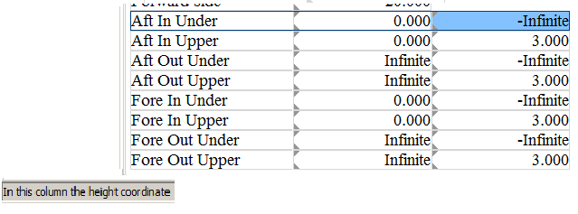
Indication, lower left, whether the cell contains a breadth or height boundary.
Calculate and print tank tables
The tank volume tables options are activated with the menu bar optie [tAnk tAbles]. It contains four suboptions that will be addressed below.
Setup: define computation scripts and output scripts
With a script the output of the tank tables is specified. Scripts come in two flavours, the computation scripts where arithmetical issues are specified, such as step size and trim range, and output scripts where quantities and units are specified. For the sake of flexibility for both types of scripts multiple versions can be specified.
Computation scripts
The computation script determines the way the tank tables are computed, by specifying:
- The name of the script. Multiple scripts may be defined, and per compartment the appropriate one should be selected>, and this script name serves for identification purposes.
- Which script is ‘default’. If a compartment does not refer to a specific script, this ‘default’ is used at the calculation.
- The calculation step, which is the vertical step (in meters) on which the table is calculated.
- The output step, which is the step on which the table is printed. If in a script table in the first column a distance-quantity is used (such as height, ullage or sounding) than the table is printed with this step size in meter. If an other quantity is used in the firstcolumn (such as volume) than the table is printed with a step size that roughly corresponds with the output step in meters as specified here. In order to prevent the combination of a large computation step and a small output step, in the end the maximum of the two is applied.
- The trim, or trims. A single trim can be specified in this cell directly, for multiple trims a dedicated subscreen appears after pressing <Enter>.
- Whether tables should be produced for all angles of inclination. If filled in with ‘yes’ then tables will be produced for all combinations of the trims as specified here in Layout, and the angles as given in Config (as is discussed in Angles of inclination for stability calculations). If the inclinations are modified in Config then the possibly existing tank sounding tables are not declared invalid automatically. So, they should be explicitly removed with option ‘remove alle calculated tank tables’, please also consult Remove: remove alle calculated tank tables.
Output scripts
An output script specifies which parameters are to be included in a tank table and in which units. Those parameters are:
- Height, which is the height of the level of the liquid related to the PIAS system of axes, see sketch below. When a tank table is computed with trim, large positive or negative ‘heights’ can occur, because the ‘heights’ are defined from baseline at Lpp/2. The first height is at a just empty tank, the last height at the tank just completely filled.
- Ullage, this is, with a sounding pipe of at least two points, the ‘dry’ distance through that pipe between the last (=highest) point and the liquid level. As discussed in Sounding pipe, a “pipe” may consist of only one point. This is then the ullage reference point from which is measured downwards, and which is therefore intended to lie above or at the top of the tank. The ullage is then the perpendicular (i.e. taking into account trim and heel) distance between that point and the liquid level.
- Sounding, which is the complement of ullage, i.e. the ‘wetted’ distance through the pipe between the first (=lowest) point and the liquid level. A “pipe” consisting of a single point defines the sounding reference point, from which is measured upwards, and which is intended to be somewhere at the bottom of the tank. The sounding is in this case also the perpendicular distance between that point and the liquid level.
- Volume, weight, VCG, LCG and TCG will speak for themselves.
- ITransverse and ILongitudinal are the transverse and longitudinal moments of inertia.
- FSM's are the free surface moments.
- Pressure, for which the corresponding compartment must be equipped with a pressure sensor, the position of which can be specified in the menu of Special points / openings. The pressure is, obviously, calculated perpendicular to the waterline (= liquid level in the tank).
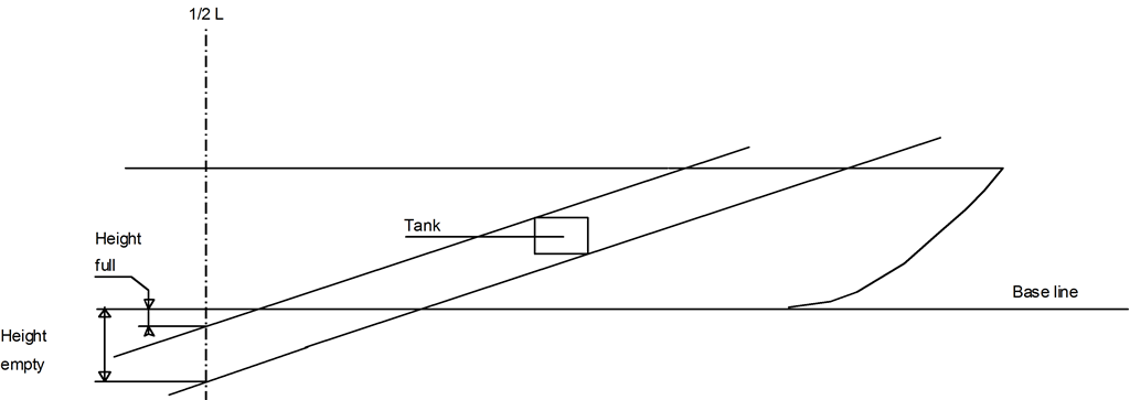
Definition of `height' in a tank table.
Each output script has a name so for each compartment the script to be applied can be identified easily. Per script it can be specified which quantities should be printed, in which order and in which unit. Each script has an input screen the quantities and units. The first row of this screen will be the first column in the table, the second row corresponds the the second column etc., so you can specify freely the desired number of tank table columns. The last column of the script contains the label ‘category’, which is only applicable for the quantities sounding, ullage and pressure. This ‘category’ is a letter from A to J and its purpose is to identify the applicable sounding pipe or pressure gauge. For multiple pipes or sensors can be defined per compartment, and for each tank table it should be specified which of those to use. Pipes and sensors also possess such an A to J category, so serves as identification mechanism.
Calculate: compute the tank tables
With this option the tank volume tables of all selected compartmemnts are calculated, according to the specified computation scripts, and according to the setting ‘tables with everywhere the maximum free surface moment’ of Config and as discussed in Settings for compartments and tank sounding tables. With the tank tables also the computation time is saved, so a re-computation can be done rather efficiently, because only those tanks that have been modified since the last computation are actually re-computed. If an unconditional re-computation of all tanks is deemed neccessary, then all existing tables should be removed, this is discussed in Remove: remove alle calculated tank tables. By the way, with the switch ‘re-calculate tank tables automatically’here in Layout, see Layout project settings and function colors, the tables are being calculated whenever required, so with this switch set it will not be neccessary to calculate here explicitly.
- Attention
- Tank volume computations are, obviously, based on the shape of the tanks, but also on the location and shape of the hull frames (as defined in Hulldef). This implies that (even for tanks that do not intersect the hullform) the number of frames may have its effect on the tank computation result. For a discussion on the effect of the number of frames reference is made to Number of frames.
Print: print tank tables
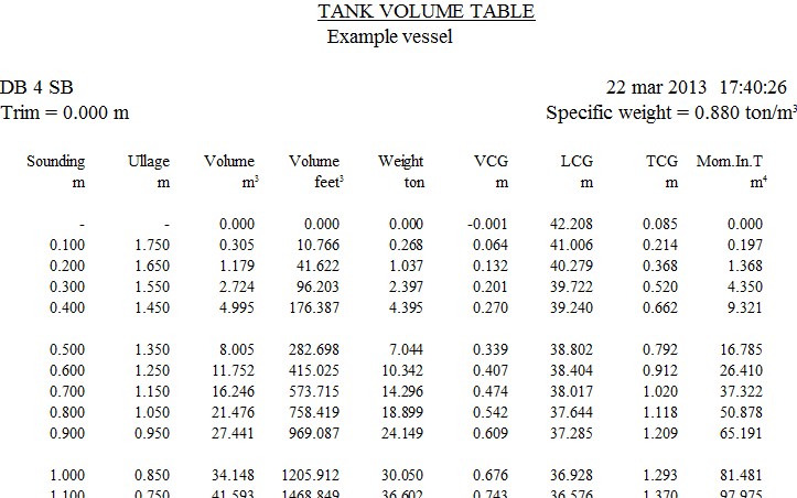
Example of a tank table according to output script.
With this option tank tables will be printed, in a number of variants (from which three are included here as example in the figures):
- According to the output script, which allows for a good control over layout and content of the tables. If sounding or ullage is included in this table, it may contain a remark that the sounding pipe is too short. This means that the tank can be filled to a higher level than the top of the pipe, and implies that at a reading at exactly the top of the pipe, the volume may have any value between the volume which corresponds exactly with that level, and the maximum volume. In order to have an indication of the maximum volume, that value is printed. However, an additional line may be printed which is valid for a level exactly through the top of the pipe (as well as an additional line with elucidation).
- Litre tables, or sounding/litre tables, to put it more precisely. This table does not contain other data, so it is rather condensed.
- Trim tables, where for a range of trims the volumes are depicted. Trim tables come in two fashions:
- On basis of sounding and ullage, where at each line at the sounding (in meter) for each trim the corresponding volume can be read. If a sounding pipe contains more than one point, the corresponding ullage is also included.
- On basis of pressure, where at each line at a certain pressure (in mm water) for each trim the volume can be read.
- Correction tables, which represent the deviation in tank volume due to list and trim. These kind of tables are a bit outdated, for if the volumes are directly calculated at multiple trims (e.g. with the ‘trim tables’ option above) such corrections are not neccesary at all. Anyway, the modus operandi with the correction table is:
- Find the tables of the intended tank (there are two tables for each tank).
- Look up the first correction value in the trim table at the measured sounding/ullage and trim.
- Look up the second correction value in the list table at the measured sounding/ullage and list.
- Add those two correction values (which are in millimeters) to the sounding/ullage. This is the sounding/ullage that can be used to read out the tank volume at zero trim and list.
- Summary, which produces a table summarizing maximum volumes and COG's etc. of all (selected) compartments. Please bear in mind that maximums of volume and moments of inertia are really the maximum values that occur anywhere in the tank. They do not have to belong to the same filling level, e.g. with a U-tank the maximum volume is reached, obviously, with a completely filled tank, while the maximum moment of inertia will occur at partial filling, with the liquid level in the bottom part of the tank.
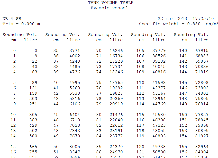
Example of a table of litres.
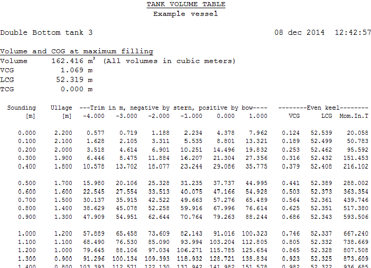
Example of a trim table.
Remove: remove alle calculated tank tables
With this option all calculated tank tables will be removed. Actually, there is no reason to do so, because the program keeps track of the tanks whose shape has changed since the last calculation, so the tank tables is known to have become obsolete and must be re-computed. Exceptions occurs if the switch ‘tables with everywhere the maximum free surface moment’ is toggled or the angles of inclination are modified in Config (and as discussed in Settings for compartments and tank sounding tables and Settings for compartments and tank sounding tables respectively). In those cases the existing tables have to be removed manually with this ‘remove’ option. And, if for whatever reason you wish to remove tank tables, this is also the option to use.
Areas: print table of outer surface areas
With this option the outer surface area of the (selected) compartments will be computed and printed, with the purpose to serve as approximation of the compartment's paint area. When applying this table one should realize that:
- Construction parts in the compartments and on the outer walls are not defined in PIAS, so their areas are not included.
- With compartments adjacent to the shell the computation is based on the envelopped frame lengths, so the accuracy is more or less proportinal to the number of frames within a compartment. Additionally, for these compartments the area computation will not be accurate if in an asymmetrical hull shape the frame locations — as far as falling within the compartment — of the PS hull are not the same as for the SB hull.