PIAS Manual  2024
Program for the Integral Approach of Shipdesign
Layout: Design and utilization of the ship's layout
Layout is the PIAS module with which the internal geometry of the ship is recorded, managed and used. It goes without saying that that internal geometry can consist of bulkheads, decks, compartments and other spaces, but it may also contain additional data, like the weight group of the volume of a specific compartment, or the sounding pipe geometry. A description of the background of Layout can among others be read in the Compit'11 paper. Briefly, Layout offers the following modelling possibilities:

  • Defining compartments through compartment boundaries.
  • Defining continuous bulkheads and decks, between which the compartments are formed.
  • Support by means of reference planes, to which compartment coordinates as well as bulkheads and decks may refer.
The first two methods are mutually convertible, which means that one is able to convert from bulkheads/decks to compartments as well as vv. Briefly, Layout offers, furthermore, the following functions in the field of internal geometry:

  • Calculation of tank tables, trim correction tables etc., in a variety of formats.
  • Output of a schematic tank plan and 3D views of compartments.
  • Definition of the layout of a 2D subdivision plan, and its output to paper, bitmap or DXF file. This subdivision plan may function as basis of the general arrangement plan.
  • Function as server of internal geometry, which is able to respond to requests of other software applications. So, for example, the shape of a deck or of a compartment can be made available to other (CAD)software upon request.
  • Import and export of the internal geometry in XML format.

Definitions and basic concepts

Definitions

Plane
A plane is endless, and can have any position in the space, can therefore also be angled. But every cross-section of a plane is straight, so it cannot be curved or twisted.
Physical plane
A physical plane is a plane which can be limited, and can be the separation between subcompartments. As a rule, physical planes are used to model bulkheads and decks.
Reference plane
A reference plane is a plane to which the sizes of other entities can be normalized. The use of reference planes can be useful for later design modifications, but its use is not obligatory.
Orthogonal plane
A plane which is oriented in one of the three main directions, so an ordinate plane, waterline plane or buttock plane. Planes with a different orientation are labelled ‘angled planes’.
Compartment
A compartment is a closed, watertight space in the ship; as a result, one can pour water in a compartment and the water will not get outside of it. As for the manner of modelling, there is no distinction between a wet compartment, a dry compartment, a hold, an engine room or a closed quarter deck. In short, anything that is watertight is a compartment for PIAS. A compartment is built from one or more subcompartments.
Subcompartment
A subcompartment is a ‘logical’ building block of a compartment. A subcompartment has no physical meaning, the concept has only been introduced to make it a bit orderly for people to define a complex compartment. A subcompartment can be positive or negative, in the first case the shape of the subcompartment is added to the others, in the second case it is deducted. A subcompartment can be one of three different types, which will be explained below:
With coordinates
A subcompartment of the type ‘with coordinates’ is simply limited by typed coordinates (which may refer to a reference plane). The user is free to define subcompartments of this type overlappingly, or to let holes exist between them. An example of a subcompartment of this type is depicted in the figure below, where with four coordinate pairs a part of the ship is ‘carved out’, which constitutes the subcompartment. Please see that the coordinates may very well fall outside the ship hull boundary, if that is the case the ship boundary is simply taken also as subcompartment boundary (by the way, if shell or deck are indeed a subcompartment boundary, than it is even beter to use ∞ as boundary than to exactly use the shell breadth or deck height. See also Intersection with the hull shape).
Space generated between planes
A subcompartment of the type ‘space generated between planes’ coincides with the space generated between physical planes. This type of compartments is unique, and cannot overlap between themselves.
External PIAS hull form
A subcompartment of the type ‘external PIAS hull form’ (a.k.a. external subcompartment) is meant for a subcompartment being too complex for one of the other types, for example because its limits are curved, such as those of a gas tank. Such a subcompartment can be defined with a PIAS shape design or definition module, as if it is a regular ship shape. Subsequently, that ‘hull form’ is indicated as subcompartment, after which it is integrally included in all following steps and calculations. See the example below, where a forty meter gas tank is defined as ordinary PIAS hull form — with Hulldef or Fairway — and subsequently positioned in the actual vessel, with a longitudinal shift of twenty meters and a vertical shift of one meter, which brings the tank to its real position.
Attention
From these definitions follows an important difference between a subcompartment of the type ‘space generated between planes’ and the other types. For those other types have their own shape definitions, that form one whole with non-geometric characteristics, such as their names and permeabilities. But a space generated between physical planes always has a shape of its own, also without a subcompartment being assigned to it. Normally, a subcompartment of the type ‘space generated between planes’ is assigned to such a space, but that is not necessarily so. When no subcompartment has been assigned to such a space, that is reported by the program as non-assigned space. Functions are available in the GUI to assign such a space to or to unlink it from a subcompartment. The last is simply done by removing the subcompartment from the tree view, the space between the physical planes will remain, however.
layout_coordssubcomp640_EN.png
Subcompartment type ‘with coordinates’.
layout_externcomp768.png
Subcompartment type ‘external PIAS hull form’.

Use of different types of subcompartments

There are three types of subcompartments, as defined above. They can be used interchangeably at random, the use of different types of subcompartments within one compartment is also allowed. Although the user is entirely free to choose the type, there are still a few directions to be given:

  • The use of physical planes is practical, firstly because the nomenclature can be made much faster with them, and secondly because the bulkheads and decks are known explicitly with them, which may be useful in the event of subsequent work or computer applications. The subcompartments that are genenerated between the planes are of the type ‘space generated between planes’, the word speaks for itself. Although this type of subcompartment in principle can be applied anywhere, it could be practical to limit its application to the larger spaces that are bounded by the primary physical planes. Suppose one would like to define, for example, a fuel oil day tank in this manner, then that would very well be possible, but then one would end with six physical planes. And in the event of a multiple of such tanks the number of physical planes will be very large, that large that one can easily lose track of the situation. Such a tank could perhaps better be defined as ‘with coordinates’, if neccessary using reference planes so that later design modifications can be processed faster.
  • The type ‘with coordinates’ can be used anywhere where the subcompartment boundary consists of the hull shape, combined with (maximally twelve) boundary points. This definition is conceptually simple, overlapping subcompartments can also be defined with this, by the way, which can be an advantage or a disadvantage, that is not relevant right now, but one should be well aware of this.
  • The type ‘external PIAS hull form’ is meant for subcompartments with non-flat boundaries. Subcompartments with flat boundaries (which may very well be angled) can be defined in a more practical manner with another type. By the way, subcompartments of the type ‘space generated between planes’ and ‘with coordinates’ are always trimmed by the ship shape, save that of the type ‘external PIAS hull form’.

Naming convention for compartments etc.

Names of (sub)compartments, reference planes and physical planes can be 50 characters long, while all visible characters are allowed. Compartment names must be unique, which is not a basic requirement in itself, but in order to keep a compartment collection orderly it has been decided upon to require this. Names of physical planes need not be unique, it might occur that there are planes with different shapes, but that they are still at the same position, so one can give them the same name. It is doubtful whether this is practical, but that is up to the user. Reference planes have infinite dimensions, so there is no need to have planes at the same position, and it may therefore be required that their names are unique. Subcompartment names only matter within one compartment, so it is not necessary that they have a unique name. When copying a (sub)compartment or reference plane, the copy gets the name of the original with the addition ‘(copy)’. At least, if there is place left for that and when that name is not yet in use, otherwise the copy keeps its original name.

Links to subcompartments

As mentioned at the definition of subcompartments, these can be positive or negative. It is not necessary, but a positive and a negative subcompartment are often used to model exactly the same space. For example, a fuel oil day tank in the ER as positive subcompartment, and exactly the same space as negative subcompartment which is deducted from the ER. It may be practical in such cases to define the shape of that subcompartment not twice, but only once, and to make a link to the second one. The advantage of this is that a geometry modification in one subcompartment is directly applied to the second one.

Such a link only applies to the shape and the name, not to the permeabilities (μ). There are sound reasons for that, because permeabilities may vary, like in our example where when the μ of the MK is 85%, that of the subcompartment to be deducted must also be 85%, because there would be more volume deducted than added. But the μ of the fuel oil day tank is of course 98% (or any other permability chosen by the user).

Intersection with the hull shape

Subcompartments of the type ‘with coordinates’ and ‘space generated between planes’ can be defined beyond the hull shape, typically to plus or minus ∞ (which can be defined by typing a <I> resp. <-><I> instead of a number, from infinite). In that case, the intersections between subcompartment and hull shape are determined automatically. The hull shape itself can be defined through frames (with module Hulldef) or as solid model (with Fairway). In the latter case, an entire planes model of the hull is available with which any subcompartment intersection can be made. But in the event of a frame model, there are only frames, there is nothing in between. That does not matter at all, PIAS has (traditionally) sufficient methods to arithmetically find an adequate solution, but for drawing the program must be driven back on interpolation of a subcompartment plane with those frames. In case of a longitudinal plane, such as a deck or longitudinal bulkhead, there will be in general sufficient intersections between that plane and the frames, so that a sufficiently accurate intersection line can be drawn. But in the event of angled bulkheads it is very well possible that there are only a few intersections with the frames. In theory, the intersection line can be drawn on the basis of these intersections, but as their number is small, its accuracy can be low. There are two options here, the first one is to give a shrug, because we are only dealing with a picture and not with the calculation results, and the second one is a more complete definition by means of more frames, that can be quickly generated, for example, with Fairway.

Menu with properties of planes

layout_editplane.png
Menu with plane properties.

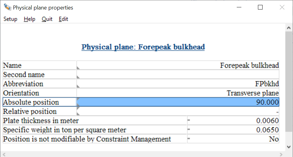
On multiple locations in Layout properties of a reference plane or a physical plane can be given in a text menu, from which an example is depicted above. Its parameters are the same as discussed in List of physical planes. If the <F5> function key is pressed on the cell ‘Absolute position’ or ‘Relative position’ then an extended menu with the plane geometry pops up, as discussed in the next paragraph.

Popup menu for geometry of points or planes

layout_vlakorientatie.png
Popup menu with parameters of orientation and position of a plane.

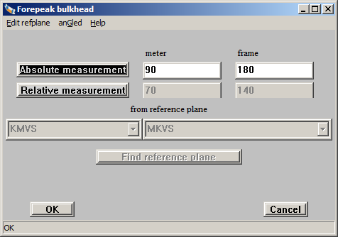
This menu is used to define the orientation, which is the direction and position, of a plane. Not only of a physical plane, but also of a reference plane. Here one can fill in:

  • The position in metres of the plane (for definition and conditions reference is made to List of physical planes}.
  • The position in frames (in case of a transverse bulkhead or transverse plane).
  • Possibly the relative position, which is the position in relation to a reference plane.
  • When the plane has been entered referentially, then the reference plan in question can be chosen in such expendable row, either by its abbreviation (left field) or by its entire name (right field).
  • As alternative for browsing through the reference planes list with those openklapbare rows the function [Find] can be used. For that one types the plane abbreviation in the left row (or in the right one its entire name) and presses the [Find] button.

Furthermore, this window consists of two functions in the upper bar:

  • [Edit refvlak], to jump to the reference plane menu, in order to add or adjust a reference plane.
  • [anGled] to change an orthogonal bulkhead or plane into an angled plane. See Angled planes for more details. This function is not always available though. For example, when one changes a reference plane this is lacking, since one would be able then to convert a reference plane, for example, from transverse to angled, as a result of which all references of other transverse planes to this reference plane would be senseless.
  • [Help reader], opens the familiar F1 help reader.
  • [Help]→[Keys], with which the list of shortcut keys appears that is applicable in this window:
EnterNext input field
TabNext input field
Shift TabPrevious input field
Ctrl-ASelect everything in box
Ctrl-DelRemove everything from box
Alt-OOK
Alt-CCancel
Alt-RRelative
Alt-AAbsolute
Alt-ZFind reference plane
Alt-TTransverse bulkhead (only applicable to a new plane)
Alt-LLongitudinal plane (only applicable to a new plane)
Alt-DDeck (only applicable to a new plane)

So, this menu can be used to define the orientation of a plane, or to specify that a plane lies on a certain, fixed, distance from a reference plane. More or less the same menu is used to define points with respect to a reference plane. This popup menu is invoked by pressing <F5> in the cell with a coordinate of the point. Two more remarks ons reference planes:

  • Those can be defined in the GUI, as well as in the alphanumeric table as discussed in List of reference planes.
  • If a coordinate is given relative, then in all input windows, in the status bar at the bottom, th erelative as well as the absolute value is presented from the cell where the text cursor resides.

Angled planes

layout_schuinvlak.png
Definition menu angled plane.

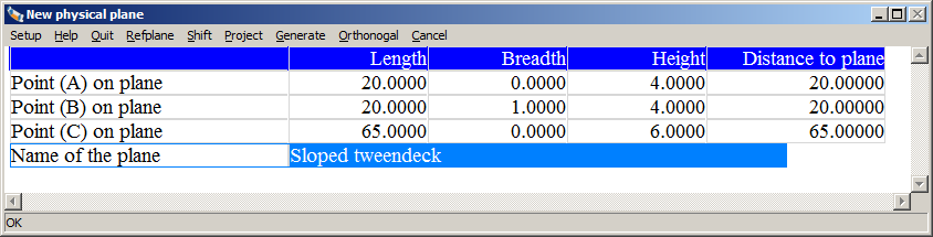
The orientation of an orthogonal plane, that is a transverse plane, longitudinal plane or horizontal plane, is entirely recorded with its type and one digit. In order to record an angled plane, however, more data are required. There are innumerable manners in which an angled plane can be recorded, but in Layout has been opted for doing this by means of three points in the space, because this is considered most intuitively. Those three points are in a menu, an example of which is given above. This menu essentially includes for any of the tree points a row, with in the columns the length, breadth and height coordinates of that point. As a matter of fact, these points are unrelated to any other point of the ship or its subdivsion — although the are fit to be linked to a reference plane. The last column contains the distance from that point to the angled plane. For the plane is not directly adjusted to the position of the three points, but for reasons of safety it has been chosen that the function [Generate] must be called upon there later on. Other functions that are available in the upper bar are:

  • [Shift]: shift this point to the plane, along the axis of this point. So, for example, if the text cursor is located on the ‘height’ coordinate this will result in a shift in vertical direction.
  • [Project]: project this point onto the angled plane, perpendicular to this plane.
  • [Orthogonal]: reshape this plane to an orthogonal plane that is most similar to this angled plane.
  • [Cancel]: leave this menu without saving the modification.

Limited positioning of a physical plane

The constellation of physical planes also fixes the nature and shape — or, put another way, the topology and geometry — of the enclosed spaces, the compartments. That's nice, but it also introduces a limitation because planes cannot be passed by their immediate neighbors; that would, after all, compromise the entire ‘logic’ of the subdivision. That can extent further than one might think at first glance, because planes can also indirectly (by means of reference planes) get a location. Thats all internally monitored in Layout, and if one would place a plane beyond its topological limit it is pushed back to its extreme limit. No warning is given on that — that might in fact lead to rather long warning lists, from which nobody benefits — but at least you now know the reason if a plane does not pass a certain location.

Compatibilitity with the former compartment module of PIAS

Around 1985 the PIAS module Compart was developed, for the definition of compartmentsm, calculations of tank tables etc. The current module Layout, which was developed in the years 2010-2012, serves the same purposes, but is much more extensive, for example because of the support with explicit decks and planes and a GUI. Compart files can be read in Layout, but this has to be done manually, see Import PIAS compartments from pre-2012 format. If, on the basis of these compartments, subsequently physical planes are being generated it may be useful to clean the compartments first, see Clean pre-2012 PIAS compartments.

Constraint Management

Attention
Constaint management makes extended use of the bulkheads and decks module (40.100.0) for Layout, and will only work as intended if your model exclusively makes use of this module to define its compartments.
Constraint management will attempt to satisfy the defined constraints by changing the position of any physical plane not locked via the 'Position is not modifiable by Constraint Management' option in List of physical planes. It is advised to make a backup of your model before evaluating the constraints.
Layout is equipped with a constraint management module. Using the constraint editor constraints can be created, edited and deleted. Constraints can be linked to compartments and physical planes in Layout. Then, using the constraints balace, the importance of the various constraints relative to each other can be set, and the module will propose a design change which complies to the active constraints.

More information on the purpose and operation of constraint management can be found here and here.

Constraint definition

Constraint Management is restricted to address the constraint problem as far as it can be included in a processing time that allows interactivity. Currently only constraints that deal with plane positions, areas and compartment volumes are considered.

Constraints can be categorized by two distinct properties, that we call groups and types. The group the constraint belongs to says something about how the constraints relates to the geometry of the vessel. Four different groups are identified:

  • Amount (e.g. number of bulkheads)
  • Position (e.g. tanktop position)
  • Area (e.g. engine room area)
  • Volume (e.g. cargo space volume)

It is important to note that the group amount is present, but is purely a 'bookkeeping' tool. This is because the Constraint Management feature works by changing the position of the physical planes of the model. It can not actually create new geometry features.

The second property of a constraint is its type. This type conveys the meaning of the numerical value of the constraint. Four types are identified:

  • Minimum (at least..)
  • Maximum (at most...)
  • inLimit (in between limits)
  • outLimit (outside of limits)

Creating and editing constraints

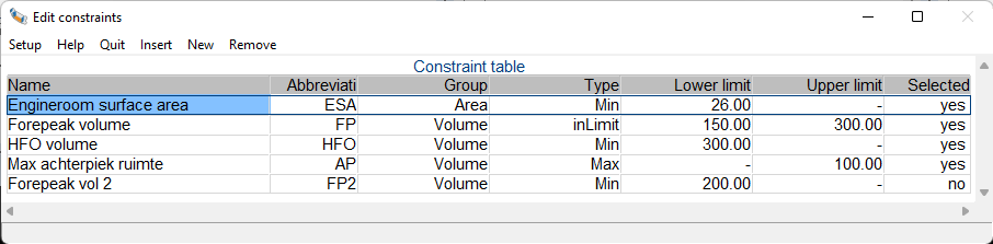
The input table for the constraints can be opened via the menu bar in the graphical user interface: cOnstraints -> edit constraints. A constraint is defined by a name and abbreviation, its group, type and the associated upper and/or lower limits. Lastly the constraint can be set to inactive to disregard it in the constraint evaluation step.

An example of a constraint table is shown below.

layout_constraint_table_example.png
Constraint table

Linking constraints to the model

After a constraint has been created it needs to be coupled to its compartment or physical plane. This can be done by opening the compartment properties (see Number of constraints) or the physical plane properties (see List of physical planes), and then setting the number of constraints value to the desired amount. Then, for that number of constraints, a constraint from the constraint table can be selected.

Constraint evaluation

An evaluation can be performed from the menu bar via cOnstraints->evaluate. Constraint management will attempt to find a solution that satisfies all active constraints.

As the various constraints probably require different things from the vessel, finding the right design compromise that satisfies all constraints can be a challenge. Often, not all the constraints are equally important, or they influence the design changes unequally and should thusly be weighted differently. Since the relative importance of the constraint is dependent not only on the specific constraint itself, but is also relative to the other active constraints in the model, the assigning of the relative importance to the active constraints is left to the user, in order to push the design in the direction that they desire.

By opening the constraint balance window the weights of the various active constraints that are linked to at least one compartment of physical plane can be set relative to each other. This can be done by the position of the slider in the vertical trackbar. Each trackbar is titled with the abbreviation of its constraint, the constraint type, and below are in order the set upper boundary value, the current value, and the lower boundary value. If the current value does not comply with the constraint it is printed in red for easy identification.

Below is an example of the constraint balance window:

layout_constraint_equalizer_example.png
Constraint balance

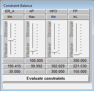
After the sliders of the constraints are set to the desired positions, the 'Evaluate constraints' button at the bottom of the constraint balance can be pushed to attempts to find a solution that satisfies all the constraints. This is done by moving all the physical planes in the model, except those that are set to not be modifiable by constraint manager. The solution is optimized for the smallest repositioning of the physical planes, so as to stay as close as possible to the designers intent when setting up the model.

Main menu

Having started up Layout, one enters the main menu, the various options of which are explained in more detail in the following sections.