PIAS Manual  2024
Program for the Integral Approach of Shipdesign
Loading: loading conditions, intact stability, damage stability and longitudinal strength
With this module loading conditions can be defined, and used to compute intact and deterministic damage stability, longitudinal strength and torsional moments. For a quick definition of loading conditions auxiliary tools are available, such as automatic tank reading, a visual interface for tank filling and a database of weight items.

At the start of Loading, all weight items are checked for references to tanks that have been removed. If this occurs, a choice must be made of what to do with those specific weight items. There are a few possibilities:

  • Removal of the weight items with a reference to a non-existent tank.
  • Convert the weight items referring to a non-existent tank to fixed weight items.
  • Don't do anything automatically, these references will have to be resolved manually.

If “don't do anything automatically” is selected, and these references have not been resolved manually, then this popup will return the next time Loading is started.

Graphical User Interface

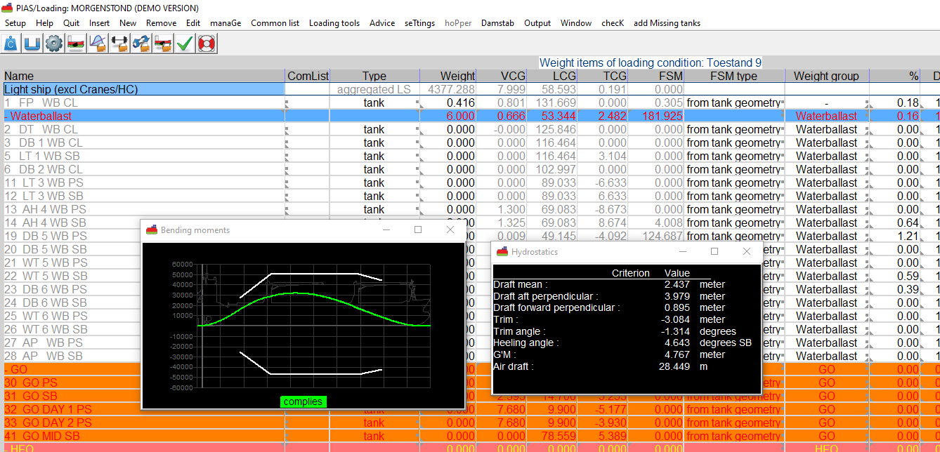
Here appears the Graphical User Interface (GUI), which can be considered as the central command window of Loading, see Main window layout. This GUI is not strictly indispensible, without it is very well possible to navigate through Loading with all functions and menu options, however, it has proven to be rather well-arranged and user friendly. The GUI is basically identical to the LOCOPIAS on-board loading software, which is derived from PIAS.

Loading conditions

With this option you enter the list of loading conditions, which can be added, removed, copied and modified from here. This list contains the following columns:

Select intact
Indicated whether the loading condition is selected for, and thus should be included in, the calculations of intact stability, longitudinal strength and torsion.
Select damage
Indicated whether the loading condition is selected for damage stability calculations.
Name of the condition
The name can freely be chosen, however, it should be unique in order to enforce some structure.
Auto-remove
This column is only included in a PIAS version with a licence for calculating the stability of hopper dredgers, and indicates that this loading condition has been generated for hopper stability. The details of these calculations are discussed in Stability of open hopper vessels.
Locked

With this cell a loading condition can be locked; it will become grey then, cannot be changed anymore, and is only available for copy purposes. Locking a condition can be useful to protect special conditions from unwanted changes.

Caution: if in a loading condition weight items from the common list (which will be introduced later on) are used, then changes to these items will nevertheless have their effects in the locked loading condition.

The menu bar of this list contains these functions:

  • [Manage], with sub-options:
    • [Move] and [Quitmove], with which a loading condition can be moved in the list of loading conditions.
    • [Design data from Layout], with which the weight group and density of all tanks in all loading conditions can be connected to the design weight group and design density of Layout.
  • [Common list], which gives access to the common list of weight items, see The common list of weight items.
  • [hopPer], where parameters can be specified for (damage-)stability calculations of a hopper dredger. Background and method of working with this type of calculations is described in Specify loading parameters.
  • [Damstab], where damage cases can be defined and other damage stability particulars can be set, see Damage cases and settings for damage stability.
  • [File], with the following sub-options:
    • [Import], which imports loading conditions — which should be available in internal PIAS format, with the .exp extension.
    • [Export], which exports all selected loading conditions to this internal PIAS format.
    • [Maestro], which exports the single loading condition where the text cursor resides to a format suitable to be imported into the finite element software Maestro (please refer to http://www.maestromarine.com). The file that is generated contains Comma-Separated Values — with file extension .csv — with the following particularities:
      • If a tank name contains a comma, it will be removed, because those are simply not allowed in the content of a .csv.
      • The permeability which is passed to Maestro is that of the first subcompartment for tank capacities.
  • [GUI], which invokes the GUI for the loading condition where the text cursor resides, see Main window layout.
  • [Output], to execute computations for all selected loading conditions. Details are being discussed in:
  • With [re-read All tanks], existing weight items which have already been read from tank tables will be read again. This option is required if compartment shapes have been changed, and the modifications should be processed in all loading conditions integrally — in which case one should not forget to re-compute the tank tables in Layout. The tanks are read on basis of the existing percentage of filling. Also tank names are read again.
  • And, finally, <Enter> brings you into a loading condition. This key opens the list of weight items of the loading conditions, which is further discussed below.

Define/edit weight items

An input window appears with all weight items for this loading condition. If weight items in the common list are defined as being a part of light ship, the first row will contain the sum of these items. This is the total light ship weight, which cannot be modified here — after all, how would such a modification be distributed over the many constituting components? If for the project weight groups are in use (please refer to Weight groups for that) that the list also contains rows with the sub totals per group. If a color is assigned to a group then this sub total is printed in that color.


The volumetric properties of the tanks always matches those from Layout where those tanks are defined. Weight group and density are connected by default to the design weight group and design density as defined in Layout. Any changes in Layout will then update these data in Loading. For each individual tank in Loading, specific weight group and/or density may be given. In this case the connection to Layout will be cut, for that specific tank. Such connected parameters are indicated by a yellow background cell color.


This list of weight items contains quite many columns — scrolling will bring you to the rightmost columns — which are:

Name

The name of the weight item.

If the temperature corrections functionality has been purchased then one can double-click on the name of a tank to enter the temperature corrections menu. See Product, temperature and density for more information.

ComList
If this is weight item from the common list of weight items (please refer to The common list of weight items for a discussion) then this column contains the consecutive number of this item in that list. In this cell a number can be entered, then that weight item from the common list is included here. Because it is not convenient to manage number from a list, with <Spatie> a box pops up with the full descriptions of the items of the common list, from which you can select. Please note that in both cases the common listitem overwrites the original row content.
Type

If a weight item is created by a loading tool, then it is assigned a ‘type’, e.g. ‘tank’, ‘crane’ or ‘containerbay’. In most cases the cells of a weight item of such a ‘type’ cannot be modified manually, after all those are being managed by the loading tool. An exception is a weight item of the ‘tank’ type, from which weight, volume, filling percentage or density can be entered, after which the other parameters (including COG) will be adapted automatically.

A weight item can be switched from such a ‘type’ to a regular (loose) weigh item with the <Space bar>. A ‘tank’ type of item has — if this functionality has been purchased — yet another option, which is the ‘flooded tank’, which is a tank in open connection with the sea.

Weight
In ton.
VCG, LCG and TCG
The Center Of Gravity, in meters from respectively baseline, APP and Center Line.
FSM
The Free Surface Moment, of a liquid weight item, in tonm.
FSM type

Different people have different visions on how to take Free Surface Moments (FSM) into account. The preferred method can be entered here, with a choice between:

  1. FSM at the true volume (and true liquid level), derived from the tank shape.
  2. The maximum FSM (of all liquid levels), derived from the tank shape.
  3. Zero.
  4. If tank filling < 98% then method 1, else zero.

If a deviating FSM has been chosen, a !-symbol is printed in the output at the FSM with the option chosen. At the bottom of the page or weight list is a statement of the chosen options. Caution: this setting is not applicable for calculations including the shift of liquid effect (as discussed in (Damage-) stability including the shift of COGs of liquid), in which case always the real behaviour of the liquid is taken into account.

Weight group
The weight group of this weight item. For a weight item the group can be chosen in two different ways, either by entering the weight group number in this cell, or with <Spatie>, which pops up a selection window of groups. The weight group can also be connected to the design weight group as given in Layout. In that case the cell is colored with a yellow background, and changes to the Layout weight group will change it in Loading accordingly. Weight groups are discussed in Weight groups, and are a convenient tool to order the weight items. If in the weight group definition menu a color is assigned to a weight group, and the column ‘in table’ is set to ‘yes’, then in the weight item list here each weight item of that group is drawn in that color.
%, Density and Volume
These three parameters are only applicable for weight item of the ‘tank’ type, and denote the percentage of filling, the density (=specific weight) in ton/m3, and the volume in m3. The density can be connected to the design density specified in Layout, similar to the weight group as discussed before.
Measured, Trim sounding and Angle sounding

In the ‘Measured’ column a Sounding, Ullage or Pressure can be specified, as long as a sounding pipe and/or pressure sensor is available. With the columns ‘Trim sounding’ and ‘Angle sounding’ the trim and angle at the time of “sounding” can be specified. Note: The ‘Measured’ column contains the measured value associated with the specified trim and angle. Other data, i.e. columns, such as weight, volume and centre of gravity are determined at trim zero and angle zero.

If this functionality is not purchased then the ‘Measured’ column is only applicable to ‘grain hold’ weight items only, and depicts the Ullage, which is the distance between the top of the coaming and the grain surface. This column is only available if configured so in the Loading settings, see Settings intact stability.

Aft and fore
Here the afmost and foremost boundaries of a weight item should be given. in meters from APP. For a ‘tank’ type of weight item these parameters are being derived from the tank shape. These parameters are only relevant for the longitudinal strength calculations, as discussed in Longitudinal strength.

Furthermore, this menu contains quite some upper bar functions:

  • [Manage], which can be used to adapt the menu layout to some extend:
    • As discussed the weight item list also contains sub totals per weight group. For overview purposes it might be handy to see only these totals, which can be achived by the [Collapse weight groups] function. [Expand weight groups] restored the usual layout.
    • With [Move] a weight item can be moved in the list, in a similar fashion as in the list of loading conditions, and the list of compartments in Layout.
    • With [Sort] the weight items can be sorted, in four different ways:
      • In the order in the column where the text cursor resides, to be precise in increasing order for the columns ‘name’ and ‘weight group’, and in decreasing order in the other columns.
      • On group and column (i.e. on group number, and subsequently in the same way as just sorting on column).
      • On group and location (i.e. on group number, and subsequently in decreasing order of location based on aft and forward boundary).
      • [Undo last sort] restores the previous sequence. Please note that with repeated sorting, or when Loading has been closed, the original sequence cannot be restored. There is no intrinsic order which can be restored.
  • With [Common list] the common weight items for the loading conditions are processed:
    • [Edit common list] calls the edit window of the common list, see The common list of weight items for a discussion.
    • [Connect] connects a weight item to the common list.
    • [Disconnect] removes the connection with common list.
  • [Loading tools] contains a number of loading tools, which are very convenient, although not indispensable:
  • With [Advice] the weight addition to achieve a certain desired position (draft and triim) of the ship. Here a popup box appears, see the example below. The ‘Given draft and trim’ block initially displays the actual values for this loading condition but these should be modified to the desired values. In the ‘Displacement’ block the differences between the desired and actual displacement is displayed. Finally the ‘Total advice weight’ block indicates where the advice weight should be located in order to achieve the desired draft and trim. A heeling angle of ‘>6’ of ‘<-6’ indicates that that angle is larger than can be computed sufficiently accurate on basis of the GM'. Pressing <OK> adds the advice weight to the loading condition, <Cancel> does not.
loading_advices_EN.png
Advice weight.
  • [Settings] is used to open a popup window where all kinds of settings for this particular loading condition can be made. This is discussed in Settings per loading condition.
  • [hopPer], is described in Parameters from an individual loading condition.
  • [Damstab] is used for damage cases and settings for damage stability. Please refer to Damage cases and settings for damage stability for more information.
  • With [Output] for this single loading condition a computation can be made, as discussed in The computations of stability and strength.
    • That with [Settings output] the output can be modified, see Output settings.
    • Besides the real computation, with [Plots tanks] sketches can be generated of the tank filling for this loading condition. The format and content of these sketches are according to the settings as discussed in Define sections for sketches of tank arrangement and damage cases. The output is send to printer, unless it is captured to a Preview on screen.
  • [Window] contains the following options:
    • [Result windows] with which the prime results of total weights, hydrostatics, stability or strength are presented via a floating window (windowlets). The contents of these windowlets are continuously updated, so the effect of changes in weight items of the loading conditions is immediately visible. An example is shown below.
loading_popup_results_EN.png
List of weight items, including two windowlets with computation results.
  • [Check] verifies compliance with the criteria for all calculations that are managed by Loading (and for which sufficient data are available). This option opens a popup window with a collection of sheets. The first sheet contains the general conclusion, and the next sheets the conclusion and prime parameters of the sub-computations.
  • [Add missing tanks] adds all newly created compartments to the current loading condition. Only those tanks are added for which the property ‘Automatic inclusion in loading condition’, Automatic inclusion in loading condition, is set to ‘Yes’.
  • [-prev] jumps to the previous loading condition in the list of loading conditions. This option skips Locked loading conditions.
  • [+next] jumps to the next loading condition in the list of loading conditions. This option skips Locked loading conditions.

Fill tanks per weight group

Loading conditions for design situations are often made with a uniform filling for each type of tank content, e.g. in departure conditions the fuel oil and fresh water tanks filled for 98%, and waste water for 10%. Modifications for the whole weight group can be easily applied via modifing the appropriate value on the sub total line. Possible modifications are: ‘FSM type’, ‘Weight group’, ‘Tank filling’ and ‘Density’. Do note that with ‘undo’ it is possible to restore the modification.

Read tanks as weight item

It has already been discussed that weight items can be of the ‘tank’ type, then they are linked to the shape of a compartment as defined by Layout. To use a tank as weight item it should be ‘read’ into the list of weight items. With the menu bar option [Add missing tanks], as described in Define/edit weight items, all missing tanks will be added. A tank can not exist twice in a loading condition, not even by means of the common list.

Settings per loading condition

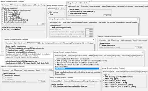
With Config general PIAS settings are specified, while here in Loading, with the option ‘Loading project settings’ Loading-specific settings can be made. But calculations of stability and strength be carried out in practice for very many different situations, and therefore it may be necessary for specific load conditions to deviate from the standard. You can with this option. If it is selected, it displays a popup window with several sheets for different topics that are discussed in the following paragraphs.

loading_settings_per_condition512.png
Several sheets for settings per condition.

Wind contour

If there are multiple windcontours available, then for each loading condition the appropriate wind contour can be selected. That can be done here; a list appears from which a selection can be made of the contours as defined in Hulldef.

Draft

In Hulldef multiple loadline drafts might have been defined, such as for ‘summer’ or ‘fresh water’ (see Maximum drafts and minimum freeboards). Here, for this particular loading condition, can be chosen which of those drafts should be included in the assessment of the condition. Furthermore, in Hulldef also minimum or maximum drafts specified (see Draft marks and allowable maximum and minimum drafts). If these are defined, here it can be selected which of those is applicable to this loading condition.

SW water

This option indicates the density (specific weight) of the outside water. Either a specific value can be used, or the standard value as defined in in Config ( Density outside water).

Stability requirements

At the definition of intact stability requirements (see Definition and selection of stability requirements for that) can be specified which is the selected one. That one will be used for the stability assessment of all loading conditions, but occasionally a loading condition must be tested against other requirements. That can be set here. To do so, choose ‘alternative intact stability requirements’, and select the stability requirement which applies to this loading condition. Obviously, only requirements which have been defined, and are valid for intact stability can be selected.

Strength

This option indicates which set of maximum allowable bending moments and shear forces are used for the longitudinal strength calculations. There are two possible options:

  • Use the standaard criteria.
  • Specificly selected criteria for this loading condition.

See Definition maximum allowable shearforces and moments on how to define these criteria.

Heeling moment

Here an additional heeling moment can be given, which is accounted for as a correction on the TCG of the displacement. This implies that this moment will be multiplied with the cosine of the angle of inclination.

Grainmoment or Livestock and fodder moment

Here the heeling moment (in tonm) due to the shift of grain can be specified. In case of grain, if stability critaria are in use ‘with grain moment’, then this moment is used in the stability calculations.

Grounding

Here can be specified whether the vessel is grounded on a single point, the location of that point (in ship coordinates) and the water depth at that location. To be somewhat more precise, the mechanism is that the ship is potentially grounded, so the local draft at the grounding location can be less than the water depth (in which case the ship is not grounded at all), but cannot be more. This grounding effect is included in all computations of Loading, while in the intact or damage stability calculation an extra page will be added with the reaction force as a function of the heeling angle (if that option has been switched on in there respective Output settings tab page). The grounding effect will only be taken into account with intact and damage stability calculations with the free to trim effect (see Stability calculation method)

Anchor handling

Additional to the regular stability output a polar diagram is plotted, which shows for each anchor chain angle the corresponding maximum anchor chain force which is still allowed by the anchor-handling stability criteria. See the example in Maxchain, Polar diagram with maximum allowable anchor chain forces for a particular loading condition. By the way, for this option it is not required to select other than standard stability criteria.

Sight line

Here the criterion can be selected to which the line of sight must be tested.

Trim optimization

Here the speed and delta displacement for the resistance-trim graph can be set.

Front page

If the front page is selected for output (at the Intact tab page), then here eight lines of free text can be given. In order to really include a line, the tick box just before it should be selected.

Product, temperature and density

If the temperature corrections functionality has been purchased then by double-clicking the name of a weight item, of type tank, in a loading condition, the following menu can be opened. This menu contains all the necessary parameters for processing temperature corrections.

Tank name
Same as the weight item, just for reference.
Include this tank in ullage report
If this compartment should be included in the cargo/ullage report then this field should be set to ‘yes’.
Product (substance)
The name of the product, which will be used in the cargo/ullage report. If no substances have been defined yet then these can be created using the menu bar function [Substances].
Conversion table

For the calculation of the cargo weight of heated hydrocarbons, the following conversion tables are available:

  • No temperature correction.
  • Correction factor per degree. The ‘Volume Correction Factor’ is calculated according to the defined temperature and the correction factor per degree (coefficient of expansion).
  • Volume Correction Factor. The ‘Volume Correction Factor’ can be defined directly.
  • ASTM tables 54(A, B and C), 55, 53(A and B), 23(A and B), 5(A and B). The ‘Volume Correction Factor’ is determined according to the respective ASTM table.
  • Nynas.

In case a conversion table other than No temperature correction is selected, this is recognisable in the weight item list by means of the yellow background colour of the name and weight of the weight item.

Temperature
The standard temperature is 15° Celsius. The volume is determined at this temperature. The actual temperature of the substance can be defined here.
Volume (not corrected for expansion)
This is the volume that is calculated according to the sounding, ullage or pressure for this weight item.
Density at 15° Celsius (in air)/(in vacuum)
The density of the substance at 15° Celsius can be defined here. If the density in air is defined, the density in vacuum is calculated automatically. These two densities are connected to each other and cannot be defined separately.
Correction factor per degree Celsius
This factor is used if the conversion table ‘Correction factor per degree’ has been selected, and calculates the volume correction factor.
Volume Correction Factor
This factor corrects the density at 15° Celsius of the substance for the actual temperature. This factor can be determined in a few different ways:
  • This factor is defined manually, using conversion table ‘Volume Correction Factor’.
  • This factor is calculated with the correction factor per degree and the difference between the standard and actual temperature. The conversion table ‘Correction factor per degree’ must be selected.
  • This factor is taken from one of the other conversion tables.
Temperature Expansion Factor
This factor corrects for the expansion of the tank at a higher temperature than 15° Celsius. This factor is calculated automatically and cannot be defined manually.
Density at {defined temperature} degrees
Density at 15° Celsius × Volume Correction Factor.
Residue On Bottom (ROB)
Volume of the residue which will be subtracted from the volume of the tank contents.
Density × Temperature Expansion Factor
Density at 15° Celsius × Volume Correction Factor × Temperature Expansion Factor.
Weight
The weight is calculated according to: Volume (not corrected for expansion) × Density at 15° Celsius × Volume Correction Factor × Temperature Expansion Factor.

Damage cases and settings for damage stability

Under the [Damstab] option in the loading condition menu, or the weight item list three sub options can be found:

Edit damage cases

A maximum of 3000 damage cases can be defined. A damage case is a collection of compartments, as defined with Layout, which will be damaged simultaneously. After choosing this option a window appears where damage cases can be defined, and which is fully discussed in Input and edit damage cases.

Generate damage cases on basis of the extent of damage

In general, damage cases are not chosen at will, they are derived from the extent of damage as laid down in rules and regulations instead. For that purpose PIAS contains a specialized functionality, which is discussed at Generate damage cases on basis of the extent of damage.

Define stages of flooding

A maximum of ten stages of flooding can be defined. A stage of flooding is a percentage of the weight of the contents of the damaged compartments in the final, this is 100%, stage of flooding. 0% stage of flooding means the compartments are not flooded at all, so this is exactly as the intact loading condition. The 100% stage of flooding is included automatically and need not be defined explicitly. The stages here are the same as defined in Hydrotables, see Define intermediate stages of flooding. Incidentally, there are many more considerations and possibilities regarding intermediate stages, which are discussed in Internal flooding in case of damage, through pipe lines and compartment connections.

The common list of weight items

A loading condition is essentially nothing more than a set of weight items (including their properties, such as name and Center Of Gravity), Those weight items can be entered in a loading condition, however, in practice there ar emany loading conditions, which have quite some weight items in common. It is beneficial if these items can be managed commonly, which is offered by the ‘common list of weight items’. This is a small database of weight items which can be used in multiple loading conditions. Everywhere these weight items are applied they are the same, which implies that a modification of such an item in one loading condition is directly transferred to the same item in another loading condition. So, the are not copied, the are being referred to.

The use of the common list is quite handy for weight items with a certain amount of communality, such as (obviously) the light ship (or its components) and deck loads or tank filling which occur in multiple loading conditions. However, its use is not obligatory, it is a tool, not more. In principle all weight items can directly be entered in the loading conditions, however, with the tiresome effect that later changes will have to be processed manually in all loading conditions. With the common list you save yourself these troubles, and reduce the change on errors.

The menu of the common list

The common list is simply a list of weight items, just as a loading condition has one. So, the input window of the common list is similar to that of a loading condition, as discussed in Define/edit weight items. Differences are:

  • A weight item can be of a certain type, for example ‘tank’. Here an additional type is available: ‘empty ship’. The reason of existence of this type is that the light ship is often available by numerous components, while a stability calculation should be printed with simply one single aggregated light ship (for which, by the way, also a name can be specified, as discussed in Settings intact stability). With the aid of this type the program knows its components.
  • The total light ship weight (and COG) is visible (in blue) on the row just above the first light ship component. With the aid of this row the light ship components are ‘foldable’, which means that by typing something there, all individual components are toggled between invisible and visible.
  • Tanks and other components other than ‘empty ship’ and ‘free weight item’ can only be added to this list via the [Connect] option, as discussed in Define/edit weight items, in a loading condition.
  • The sub total line does not support any weight group modifications as described in Fill tanks per weight group.

Also the available upper bar functions have all been discussed with the loading condition list, with the exception of:

  • [Output]→[Print common list], which prints the common list.
  • The [Import] function, which reads a text file of light ship components — which should be available in (ASCII) format, with the project file name.klm extension. If the file contains N components then the file should contain N+1 lines, see the spec below. Please take note of the last line with zero's and the text ‘stop’.
Weight(1)VCG(1)LCG(1)TCG(1) Aft boundary(1)Fwd boundary(1)Component name(1)
Weight(2)VCG(2)LCG(2)TCG(2) Aft boundary(2)Fwd boundary(2)Component name(2)
10.1258.75424.20-0.52 20.1(2)31.2Tandwielkast
Weight(N)VCG(N)LCG(N)TCG(N) Aft boundary(N)Fwd boundary(N)Component name(N)
.....................
000000stop

The computations of stability and strength

In this section the merits will be discussed of the several Loading computations: intact stability, damage stability, longitudinal strength and torsional bending moments.

Output settings

Intact

At this tab several output options can be selected. From the listed components it can be specified whether they should be included in the output. If output for a selected option is still not produced, the reason might be that the option is not purchased or otherwise not available.

The option ‘Front page’ adds a front page to each stability calculation, which contains:

  • A maximum of eight lines of user defined text, which can be given at the next tab page.
  • A summary of the total weights for defined weight groups.
  • Hydrostatics in upright position.
  • Initial transverse stability.
  • Drafts and trim.
  • Statical angle of inclination for this loading condition.

With the option ‘Moments of inertia of tanks’ an additional page with the volumetric moments of inertia of the filled tanks is printed.

Strength

This tab page facilitates in the output options for the longitudinal strength calculation.

Damaged

At this tab several output options of the damage stability calculation can be selected. From the listed components it can be specified whether they should be included in the output. If output for a selected option is still not produced, the reason might be that the option is not purchased or otherwise not available.

Cargo report

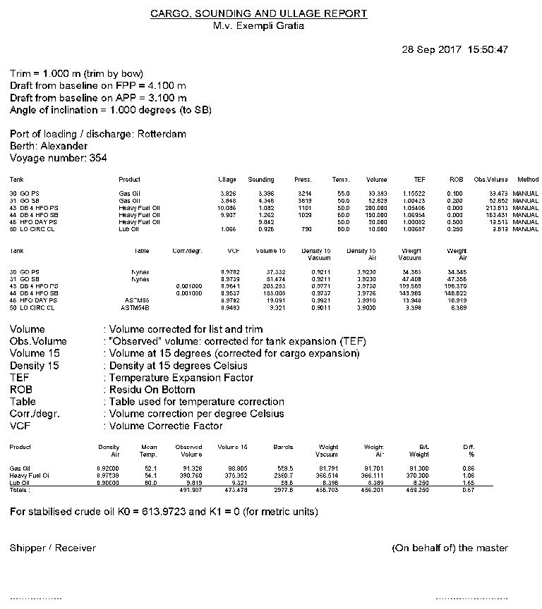
Here you can specify whether a full or short ‘Cargo/ullage report’ is desired. See Cargo/ullage report for more information.

Intact stability

To perform the stability calculations, it will be obvious that all the ship properties should be fully specified, not only hull shape and compartments, but e.g. also the light ship weight and openings. In addition, the following properties must also be set correctly in order to be able to make a complete stability calculation:

The intact stability output contains the following parts:

  1. The weight list.
  2. A table of upright hydrostatics and drafts.
  3. The table of GZ and area under the GZ curve for the different angels of heel.
  4. A plot of the GZ curve.
  5. The conclusion where this condition is assessed against the minimum criteria.

However, this is the standard output, with the different settings of Loading it can be extended or limited significantly.

Attention
If the weather criterion from the Intact Stability Code (or a criterion with a similar nature) is the most critical one, it might occur that although in the assessment of a loading condition the maximum allowable VCG is less than the actual VCG', the program reports that the loading condition complies. This might seem contradictory, but is not. The reason of this phenomenon is that according to the IS Code the rollback angle should be determined by a specific equation, in which the uncorrected VCG (that means, uncorrected for free surface effects) should be used.

Longitudinal strength

Longitudinal strength comprises the longitudinal distribution of shear forces and bending moments, and, if set, deflection and elevation. A hogging moment is positive, a sagging moment negative. A positive shear force at a position indicates that behind that position the aggregated buoyancy is less than the aggregated weight. These computations are based on the longitudinal distribution of buoyancy and weight.

Each weight item is assumed to have a linear distribution between aft and forward boundary, in such fashion that the longitudinal center of gravity (LCG) equals the user-specified value. For example:

  • A weight item of 100 ton, with and LCG at 50, and boundaries at 40 and 60 m.
  • A weight item of 75 ton, with and LCG at 50, and boundaries at 40 and 70 m.

Have distributions according to the figure below.

loading_weight_distributionEN.png
Weight distributions of the two examples.

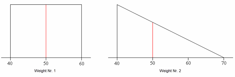
If the LCG is not within the middle 1/3 between the forward and aft boundary, then the distribution becomes partially negative. In some cases this is realistic, for example with a crane where the center of gravity of the load is even completely outside the boundaries, and sometimes it is unrealistic. Therefore it is verified at the longitudinal strength calculation whether the LCG is outside the 1/3 boundaries, and if so a warning is displayed. Also with tanks that are strongly curved in the longitudinal direction it might occur that the LCG exceeds these 1/3 boundaries. This is always considered unrealistic — the distribution of liquid in a tank can never give negative values in the weight distribution — so in these cases the aft or forward boundary is adapted in order to bring the LCG exactly to the 1/3 or 2/3 location.

If maximum allowable bending moments and shear forces have been defined (to do so please refer to Definition maximum allowable shearforces and moments), the actual bending moments and shear forces will also be presented as percentages of the maximum values.

Then the conclusion is drawn, which represents whether all moments remain below the maximum allowable values. Please note that evaluation of actual moments against maximum allowable values is also performed at intermediate values in-between the read-out points. The maximum allowable value at these intermediate positions is found by lineair interpolation. This evaluation at intermediate points might affect the overall conclusion. So, it might occur that all read-out point values are less then the maximum allowable values, while the conclusion still is drawn that this loading condition does not comply. Somewhere between the read-out points the interpolated maximum will be exceeded in such a case.

There is also the option to calculate and output the so-called ‘Envelope curve’. With this option, the envelope upper and lower limits are calculated of the occurring shear forces and moments based on the curves of the selected loading conditions. This envelope curve can be used to determine how strong the ship should be at certain longitudinal positions. Thus, it is really a design tool.

Deterministic damage stability

Plain deterministic damage stability

With this option for all combinations of selected damage cases, selected loading conditions and intermediate stages of flooding damage stability calculations will be produced. Suppose there are three loading conditions, five damage cases and two intermediate stages, then 3 x 5 x (2+1) = 45 damage stability calculations will be made. A regular output contains the following data:

Identification
Name of the damage case, the stage of flooding and the intact weight data.
Special points
If any margin line points have been defined (with Hulldef ), then here the distance from the waterline to the margin line will be printed. If a non-watertight openings have been defined, the angle where this opening will be flooded is printed, as well as the distance from the waterline to this opening. Distances are not given in PIAS' standard system of axes; instead the distance is measured between point and waterline, measured perpendicular to the waterline.
Ingressed flood water, outflown intact content
For every damaged compartment, at angle of equilibrium, the following particulars are printed:
  • The weight of the contents of the intact compartment (Wintact).
  • The density of the contents of the intact compartment (SWintact).
  • The weight of the contents of the damaged compartment (Wdamag).
  • The density of the contents of the damaged compartment for this stage of flooding (SWdamag).
Table of stability parameters at larger angles

The first line indicates to which side the vessel is heeling, SB or PS. The module automatically determines the side with the worst stability, however, this can also be configured otherwise, please refer to Calculate damage stability with a heeling to for this setting. Subsequently, for every defined heeling angle the following particulars are printed:

  • Heeling angle (in degrees).
  • Displacement excluding the possibly spilled cargo and including the weight of the flooded compartments.
  • Draught at LPP/2.
  • Total trim on perpendiculars.
  • Righting lever (meter), defined as the ratio of the righting moment and the intact displacement. So the righting lever is corrected to constant displacement (the intact displacement).
  • The dynamic stability up to this heeling angle (area under the righting lever curve) in meterradian.

When instead of, or next to, these columns the text ‘The vessel sinks’ is printed, this indicates that a non- watertight or non-weathertight opening is submerged at an angle smaller than the statical angle. Or that the total weight exceeds the total buoyancy.

Prime parameters of the damaged stability
  • Statical angle of inclination (degrees).
  • Maximum righting lever (meter).
Verification against the criteria
Assessment of this damage case against the damage stability criteria, as they have been defined in Definition and selection of stability requirements.
GZ-curve
A graph of the righting lever curve.

Calculate cross-flooding times

Attention
This is a calculation using the old method, see Background from tools for ship-internal connections in PIAS for the difference between old and new. The option discussed here can be used to calculate the time required to flood a single compartment which is connected to seawater through a single connection. In the new method, for complex systems of multiple compartments, connections and components (such as vent caps), the overflow time can be calculated, integrated with a calculation of damage stability during the flooding process.

With this option the time can be calculated which is needed to let a compartment be flooded through a cross-flooding arrangement. The purpose of this option is similar to the method of IMO MSC.362(92) (formerly IMO res. A.266), with the difference that the IMO resolution gives an approximation method, while this PIAS option applies a stepwise calculation (a time-domain simulation) — based on Bernoulli's law — which yields in general more accurate results. This application is covered by section 4 van MSC.362: “As an alternative to the provisions in sections 2 and 3, and for arrangements other than those shown in appendix 2, direct calculation using computational fluid dynamics, time-domain simulations or model testing may also be used”. The parameters which are necessary for this option must be specified at ‘complex intermediate stages of flooding’, please refer to Complex stages of flooding (before 2023).

Torsional moments

The torsional moments calculation is always performed for the upright vessel. Because of round-offs in the calculation and because the vessel might have an initial heeling in the loading condition, a residual moment at the end of the vessel might occur. To correct this the residual moment is linearly distributed over the total length of the vessel. The option to make torsional moment calculations for a grounded vessel has not been implemented.

The generated output of the calculation shows successively:

  • One or more pages with an overview of all weight items, including name, transverse center of gravity (TCG) and fore- and aft boundary. Dependent on the Loading setting setting ‘print parts of light ship summarized’ (see Settings longitudinal strength) the light ship items are printed summarized or separately.
  • One or more pages with intermediate results of the torsional moment calculations. With an increment as set in the setting ‘output increment’, for each longitudinal position the following is calculated; weight moment (tonm/m), buoyancy (tonm/m), torsional moment (tonm), the torsional moment area (tonm2) and the absolute torsional moment area (tonm2).
  • A page starting with a few lines displaying position and value of the maximum occuring torsional moment, torsional area and absolute torsional area. If maximum allowable torsional moments have been defined (read-out points, see Definition maximum allowable shearforces and moments for that), at different positions of the hullform a table is printed. In this table the actual torsion moments are printed as a percentage of the maximum allowable value. So for every location the actual torsion moment and the actual moment as percentage of the maximum allowable is printed. If this percentage is lower than 100% the value is printed in green, otherwise in red. If a maximum allowable torsional area is set, see the last setting of Definition maximum allowable shearforces and moments) then the actual absolute torsional moment area is tested against the maximum allowable value. Finally a conclusion is printed which indicates whether all torsional moments are lower than the maximum allowable. Here the same remarks applies as in the last paragraph of the discussion of the calculation of longitudinal strength, just prior.
  • A graphical presentation of actual and maximum allowable torsion moments. In a sideview of the vessel the actual torsional moment is shown presented by green curve. The red curve shows the maximum allowable values.

Sounding table

Delivers a report where for all tanks — and then for all measuring devices, i.e. sounding pipes and pressure sensors, in the tank — at trim zero and angle zero, the current sounding, ullage and/or pressure is calculated based on the current volume.

Cargo/ullage report

This option allows you to print an overview of all onboard cargoes, including their weight, temperature effect, sounding and ullage etc., see example below. This list includes only those tanks of which the detail particulars (as discussed in Product, temperature and density), at the second row ‘Include this tank in ullage report’ is switched on. Before this report is created some more questions might be asked, such as the Bill of Lading weight. Note that the weights of the Bill of Lading are only useful if the ‘Product (substance)’ is defined.

sounding_cargoullage768.png
Example of a cargo/ullage report.

Loading project settings and tools

Settings intact stability

Name of ‘light ship’ in loading conditions
It occurs quite often that the common list of weight items contains quite many components of light ship. Those need not all to be included in the loading conditions, after all that would require many pages. So, only the total weight (and COG) is included in a loading conditions, however, that items still requires a name. That can be given here.
User-specified scale of GZ-plot
The output of a stability calculations contains a GZ-curve. Its scale is selected by the program, in order to fit properly on a page. With ‘yes’ at this option a user-defined scale will be used (which can be entered one line lower: if you desire e.g. a scale of 1/5, then 5 should be entered there). All GZ-curves of all loading conditions will then be printed on the same scale.
Print moments in the list of weight items
With ‘yes’, in the intact stability output besides the weight and COG's also the moments will be included.
Print % of filling and density in weight list
If this option is set to ‘yes’ in the intact stability output each weight item will be printed including the percentage of filling and the density of the tank contents.
Print the deadweight in the list of weight items
With ‘yes’ the deadweight (and the COG of the deadweight) will be included in the output of intact stability calculations. The deadweight is total displacement minus the light ship weight.
Connect points of GZ-curve with straight line segments
A GZ-curve is usually drawn as nicely curved. And that will usually be her natural shape: a smooth curve drawn through the points formed by the calculated GZ values at the chosen angles of inclination. Sometimes, however, the trend of these points is not so smooth, e.g. when it contains a discontinuity as result of submerging an (internal) opening. The “smooth curve” method, however, does not know about these discontinuities and does its best to draw a curved line through the points, which will indeed be nicely curved, but in exceptional cases may also show a considerable loop. With this option set to ‘yes’ no curved curve is drawn, but the points are connected by straight line segments instead. In general slightly less accurately inbetween the points, but without curls at discontinuities. The reduced accuracy can be compensated for by having more angles calculated.

Settings longitudinal strength

Output increment
Enter the longitudinal interval in meter, which will be applied when printing tables of shear forces, moments etc.
Including calculation of sagging
Indicates whether sagging (as well as deflection) should also be computed and printed. If yes, then an additional row appears where Young's modulus should be given — as a rule 21000000 ton/m2 for ordinary mild steel. The moment of inertia of the midship section structure must also be specified, which can be done at the Loading project settings, see Define cross sectional moments of inertia (for calculating sagging).
Print parts of light ship summarized
By default all light ship items, which constitute the total light ship, are printed on the output. Here it can be set to print only one single, totalized light ship weight. just as with the intact stability calculations.
Weight item boundaries change with LCG
By default, all dimensions of each weight item have to be given, including LCG and aft and forward boundaries. If this particular option is switched on, then a little trick is applied, then the boundaries are shifted the same amount as the LCG, when the latter is modified.
Maximum allowable torsion area (Tonm.m)
Classification may impose a maximum on the maximum area under the torsion moment curve. Such a maximum, which e.g. is called AST by Germanischer Lloyd, can be defined at this option.

Settings deterministic damage stability

In Config the general settings for damage stability can be selected (see General settings damage stability), while here settings specifically for deterministic damage stability (which, after all, is computed by Loading) can be given.

User-defined scale of GZ-curve in damaged condition
By default, the GZ-plot of all damage conditions will be determined by the program so that it fits nicely on the paper, but if this option is answered with ‘yes’ a fixed scale can be specified by the user at the next option. In this case each GZ curve will be plotted on the same scale.
Which scale to use for GZ-plot (give X in scale 1:X)
The denominator of the user-defined scale should be given here, e.g. 5 for a scale 1:5.
Sort openings and margin line points in output
In the output of damage stability calculations all (in Hulldef) defined openings or margin line points are included in the output, in combination with angles of downflooding or distances to the waterline. With a ‘no’ for this option the output sequence equals the definition sequence. With a ‘yes’ they are sorted in increasing distance to the waterline (so, the most severe point comes first).
Maximum number of openings and margin line points to print
A maximum number of to be printed points can be given if Openings and margin line points are sorted.

Settings polar diagram anchor handling chain forces

With the general ship input data in Hulldef, paramaters can be given for maximum allowable chain forces for anchor-handling vessels, zie Anchor handler particulars. In that Hulldef menu a few sets of criteria can be selected, either NMD2007, BV2014 of IS code 2020. If the BV type is chosen, the polar plot can be produced for a user-specified angle of β (please refer to Input of specific ship data for its definition) which can be set in this menu.

Definition of weight groups

Purpose and use of ‘weight groups’ is discussed in Weight groups.

Definition and selection of stability requirements

The modus operandi of the stability criteria system is discussed in Stability criteria for intact stability and damage stability, and the specific menu to enter stability criteria in Manipulating and selecting sets of stability criteria. In this menu it can be indicated which of the stability requirement sets is valid for the assessment of the intact stability. This is then used for all loading conditions, but it is also possible to assess some conditions against other requirements, as described in Stability requirements.

Definition maximum allowable shearforces and moments

In this overview screen all created longitudinal strength criteria are displayed and how many points for the respective boundary lines have been specified. By double-clicking on a boundary line column one can modify the corresponding boundary line.

The option standard criteria allows for easy switching between different strength criteria for multiple loading conditions, if Strength have been selected for standard strength criteria.

The defined values are used in the assessment of the longitudinal strength and torsional moments calculations.

With option [Output] the input values can be printed to paper.

The percentages, which are shown in the output, are normally calculated from the zero line, but it can happen that the upper and/or lower limit are entirely or partially below or above the zero line. In such a situation the zero line is no more insight and a fictitious zero line is determined halfway between the given upper and lower limit. This allows the percentages to be determined as before, but in relation to the fictitious zero line instead of the actual zero line. It is possible that the lower limit is above the zero line and that the upper limit, which is also above the zero line, starts at a length position greater than the lower limit. In this situation, no percentage can be determined, because determining the fictitious zero line is dependent on upper and lower limit.

Definition maximum allowable shearforces and moments

In this menu the maximum allowable boundary line can be defined as a function of the length.

The following points must be taken into account when defining the maximum allowable boundary line:

  • The length must be ascending.
  • You can define a jump, but it can only consist of two longitudinal positions.
  • That, depending on the type of boundary line, negative and positive values must be taken into account.

Using the menu bar function [Lininterpol], intermediate longitudinal positions can be interpolated linearly.

The used abbreviations used in this menu are:

  • Long.pos: longitudinal distance from App [m].
  • Frame no.: frame number.
  • Value ton: maximum allowable boundary value, shear forces [ton], bending- and torsion- moments [tonm].
  • Value kN: maximum allowable boundary value, shear forces [kN], bending- and torsion- moments [kNm].

Define sections for sketches of tank arrangement and damage cases

Purpose and use of ‘sections tank arrangement’ is discussed in Sketches of tanks, compartments and damage cases.

Definition of mooring forces

PIAS contains specialistic functionality for objects which are moored with multiple anchors. It finds equilibrium in the horizontal plane, while the vertical chain forces are included in the stability computations. In the menu the relevant chain parameters can be given. However, this menu is only available for those who have actually purchased this functionality.

Define cross sectional moments of inertia (for calculating sagging)

For the purpose of the calculation of the longitudinal sagging — such as is included in the longitudinal strength calculation if the including calculation of sagging option is switched on, see Settings longitudinal strength — the moment of inertia of the midship structure must be specified. That can be done here, in fact, for multiple cross sections that can be specified, so that the effect of the longitudinally varying moment of inertia on the deflection can be accurately taken into account. If the variation in moment of inertia can be excluded than it will suffice to enter the midship moment of inertia only. To be exact, in the two colums you specify:

  • The longitudinal distance from APP in meter.
  • The moment of inertia at that location, in meters4.

Compute tables of shear forces and moments of buoyancy

This is a bit of an outdated option, however, it still might occur that a longitudinal strength manual is required which also contains a scheme for the manual calculation. In that case tables of shear force and moments of only the buoyancy might be needed. With this option (if purchased) those tables can be produced. Calculation will be performed for user-specified drafts, for all longitudinal positions for which maximum allowable bending moments and shear forces are defined. After this option has been selected the following data can be specified in a menu:

  • First and last draft, and draft increment.
  • Trim for which the tables will be calculated.
  • Draft step for determination of draft correction (correction = (valuedraft+draft step - valuedraft) / draft step).
  • Trim step for determination of trim correction (correction = (valuetrim+trim step - valuetrim) / trim step).
  • Name of the outputfile (default extension is .LST from Longitudinal Strength Tables).

The output is not designed for printing directly to paper, after all, some post-processing will be done anyway.

Settings for ballast advice

See Ship-specific settings for ballast advice.

Generation of loading conditions for simulation RoRo operations

This facility is intended for simulation of RoRo operations, and is discussed in Generation of loading conditions for simulation of Ro-Ro operations.

Combined output

This option can be used to perform multiple kind of calculations in one single run.

Definition of output sequence

In this menu can be specified which computations should be made and printed. For each type of computation also a page numer and chapter name can be given, which will be printed at the bottom of each page. The left column, selected specifies whether the output of that line is actually included in the output to be produced. The menu bar contains the function [layout], which can be used to choose from two kinds of output sequences. The first option is [Type of calculation], where first for the first type of calculations all loading conditions are printed, and then for the second type of calculations all conditions etc. The second option is [Loading condition], where first for the first loading condition all types of calculations are printed, then for the second condition all types etc. The chapter name as given in this menu is only used with the ‘Type of calculation’.

File and backup management

Backups of the Loading data can be made and restored here. Here is also the option ‘Quit module without saving the data’. See for the details Data storage and backups.