With
Fairway it is possible to generate a lines plan from the threedimensional shape. The sections to draw, and their locations are configurable, and additional texts and size markers can be generated. An example of such a linesplan is depicted below. By the way, the mechanism behind this lines plan generation is quite similar to that for the subdivision plan from
Layout. Details will differ, however, for a better understanding the subdivision pages might be visited on
Subdivision plan. Although in this manual the line plan mechanisms will be discussed thoroughly, experience shows that a few experiments may also be instructive. And please be assured that although with an `erroneous' lines plan definition the result may be unexpected, it is not possible to ruin the underlying ship hull model.
If a hull consists of multiple solids, it may be desirable to include some in the lines plan, and to leave out others. That can be specified in the menu
[Object management].
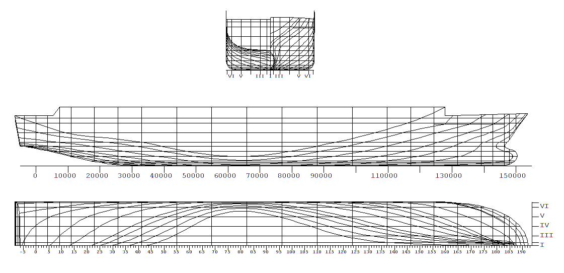
Example of linesplan, as generated by Fairway.
Definition of the layout of the lines plan
After selection this option an input window appears where a maximum of four linesplans can be composed, and where one of those can be selected for actual output. The purpose of the columns in this menu is deiscussed in the table just below. Furthermore, when you move the text cursor to a drawing and press <Enter> the menu [Views of [linesplan name]] appears, where the views of the drawing can be defined.
- Slct
- Here you can select the lines plan to be actually generated.
- Description
- Just a simple textual description, just for your own orientation.
- Margin
- Additional margin at the edges of the paper, in millimetres. The default is 10 mm.
- Border
- Whether or not a border should be drawn.
- Title block
- Whether or not to include a title block. The border and title block will not be included on output to screen or to DXF file. The title block text can be given in Enter title block texts. .
Views of [linesplan name]
In this menu the views (with a maximum of 16) of this lines plan can be specified. With <Enter> in the first column one goes one level deeper into each view - where the viewing parameters are given into detail as discussed in the paragraphs below - however, first the main properties of the views have to be defined in this menu. The purpose of the columns here is:
- Description
- A description of this view.
- Active for text
- Texts can be added to a lines plan, this is discussed in Define additional legends and in Draw and extent linesplan, on screen. These text belong to the view which is `active for text', as defined in this column. This implies that if a view is removed, then the belonging texts are removed as well.
- View
- The type of view can be chosen here, avialable types are:
- In standard directions
- These are conventional views, on the planes of waterlines, frames, buttocks or diagonals (under 45°) The applicable parameters will be discussed in Definition of views in standard directions.
- 3-Dimensional
- Threedimensional view on hullform, under a user-defined viewing angle. For teh parameters please refer to Definition of threedimensional views.
- Plate layout
- A three-dimensional view of the shiphull. The view shows the plate borders of the selected plates with addition of the name of the plate. The parameters are identical to thos of the threedimensional view, just above
- Only SAC
- The Sectional Area Curve (only of the single solid as used for this lines plan, so the contribution of possible other buoyant solids is not included). See Definition of a view on the Sectional Area Curve for details.
Definition of views in standard directions
With this option an intermediate menu opens up, with the following options:
Definition of views in the standard directions
You can specify which view should be drawn, here it must be placed and how it is formatted. An important concept in this respect is the 'selection box'. That is a thee dimensional box with user-defined boundaries, with the meaning that all hull lines inside that box will be inlcluded in this particular view, and the remainder (consequently) not. If one does want to include for example only the aft ship in a view of the lines plan, then for that purpose a box with aft limit -∞ to forward limit L/2 can be taken (and because in practice ∞ is quite large, e.g. 1000 can be used instead).
- Longitudinal lower limit selection box [m]
- The longitudinal location, measured from APP, from which the lines should be included in this view.
- Transverse and vertical lower limit selection box [m]
- Similar for the other two dimensions.
- Longitudinal upper limit selection box [m]
- The longitudinal location to where the lines should be included in this view.
- Transverse and vertical upper limit selection box [m]
- Similar for the other two dimensions.
- Transverse shift on paper [m]
- Here you can specify, in real world coordinates, the amount of transverse shift on paper or on screen. A positive shift is to the right, a negative to the left. The purpose is to be able to position the different views relatively to each other The shift of the view on paper or screen in transverse direction. A positive value means a shift to the right and a negative value means a shift to the left. The purpose is to position the different views relatively to each other. The program will always ensure that all views are visible. So this shift is not connected to issues of scale or dimsonsions of screen or paper. Because the shifts are relative to each other, there is no firmly defined zeroshift; simply take an arbitrary view with zero shift, and give the shifts of the other views relative from that one.
- Vertical shift on paper [m]
- Similar to the transverse shift. Positive is a shift upwards.
- Mirror about CL
- The view is mirrored about the center line plane. For example to be used for aftship frames in the body plan.
- Draw only visible lines
- In the Graphical User Interface (GUI) it is possible to hide individual polycurves. When selecting `yes' for this option, only the visible polycurves will be drawn in the lines plan. With `no', all visible and all invisible curves will be drawn.
- Type of measurements
- With the option [Define and generate lines plan,fwy_linesplan_screen] lines can be measured - which means that automatically legends can be allocated to lines, where the location of the line determines the value of the legend. With the present option you can choose the naming system, with choices between 'frame number', 'ordinate number', 'name of line', 'number in arabic', 'number in roman', 'automatic meter', 'automatic millimeter'. Their properties will be discussed at `Types and legends of size markers' of Properties first axis.
- Font height of measurements
- The font height of the measurements, in millimetres.
- Projection plane
- here the type of view can be spcified, with the choice from frames (a front view), waterlines (top view), buttocks (side view) or diagonals (under 45°).
Definition of threedimensional views
Defining threedimensional views is quite similar to defining a view in the standard directions, as discussed just above. The differences are:
- The option `projection surface parallel to...' is not available.
- There are two additional cells; the `angle between viewing axis and CL' and `angle between viewing axis and base line'. These are the angles, in degrees, under which the vessel is viewed, please refer to Definitions and units for the definitions.
- There is an additional cell labelled `perspective', which indicates whether this is a perspective view. If this is set to `yes' then four additional cells will appear with perspective parameters, amongst which the `distance from the eye to the objectpoint'. That object point, which is the point where the eye is looking at, is defined by means of its three coordinates in the cells just below.
Definition of a view on the Sectional Area Curve
With this choice the actual Sectional Area Curve, that is the SAC of the active solid, will be plotted. Such as SAC is only possible in a private drawing, so not in combination with other hull views. However, it still is possible to define additional legends (consisting of fixed texts) for the SAC, this will be discussed in Define additional legends.
Properties first axis
In each view two axes can be defined, which are in general used as x-axis or y-axis. With this option the orientation and system of measurements of the first axis can be given. The axis method has two important properties:
- An axis is essentially three dimensional, and is defined by means of its start and end points, so by six figures in total. In the lines plan views the axis will be projected in the same manner as the hull lines.
- Legends with the axis are placed at the right side of the axis, seens from startg point to end point.
- Draw this axis
`Yes' if the axis should actually be included in the plot, `no' if not.
- Longitudinal coordinate start axis
The distance from aft perpendicular to start point of the axis, in longitudinal direction, in meters.
- Transverse coordinate start axis
The distance from centerline to start point of the axis, in transverse direction, in meters.
- Vertical coordinate start axis
The distance from baseline to start point of the axis, in vertical direction, in meters.
- Coordinates end axis
Similar to the previous three coordinates, for the end point of the axis.
- Types and legends of size markers
With this option it is possible to determine whether size markers should be placed and to which they refer. As noticed earlier, the size markers are always drawn at the rightmost side, seen from start to end, of the axis. Nine types of size markers exist:
- Automatic meter
- Measurement of the axis in meters. The size markers and texts are automatically generated by the program
- Automatisch millimeter
- As just above, albeit in millimeters.
- Frame number
- With frame number. These whould have been specified in Hulldef, as discussed in Frame spacings.
- Ordinate number
- Measurement of the axis with ordinates. Ordinate 0 is the aft perpendicular and ordinate 20 is the fore perpendicular. Obviously, the length between the perpendiculars has to be defined properly for this purpose, see Define main dimensions and other ship parameters for that.
- Name of line
- The name of the line - simple the name as defined by the user - is used with this choice.
- Ordinal numbering arabic
- Numbers is our common western numbering system (1,2,3,4....). The numbers are the ordinal numbers of the actually drawn lines. From `aft to front', `bottom to top' and `inside to outside' the numbers are increasing.
- Numbering in Roman
- Just as above, albeit in the Roman system (I, II, III, IV....).
- Nothing
- No size markers or legends.
- Only size markers
- Only size ticks will be drawn, without legends.
- Line type for numbering
If the legend type is either `name of line', `number arabic' or `number roman', then the type of line to follow has to be entered. Possible line types are frames, waterlines and buttocks. If the legend type is `number arabic' or `number roman' then a fourth choice is present, which is `fixed increment, given on line below'. This type can be used if size ticks are required on fixed distances (for example every 5 meter), while these tick should subsequently be numbered.
- Fixed value for numbering
If the line type for numbering as given the line above is `fixed increment' then that increment, in meters, can be given here.
- Numbering about how many frames
If the legend type is `frame number', then here can be specified about how many frames should be numbered. With 1 each frame is numbered, with 5 each fifth frame.
- Dimension size marker
The desired height of the size markers in millimetres.
- Angle text legend
The angle of the text legends (which are the figures or number printed at a size marker) with the axis. With 0 the text is parallel to the axis, with 90 the text is rotated 90° counterclockwise.
- Size of text legend
The font height of the text legend, in millimeters.
Properties second axis
Completely similar to the first axis.
Define additional legends
Here additional, fixed, texts van be specified which will be included in the lines plan. The `breadth' and `height' coordinates are measured from the origin of the view which is `active for texts', in meter, on real-world scale, in the same logic as the mutual shift of the different views is given. The dimension of the text is the font height, in millimeters. The texts which are generated with the interactive measurement, as discussed in Draw and extent linesplan, on screen, will also be included in this list.
Enter title block texts
Here the text lines can be given for the title block, as it can be included in a lines plan. The name of the ship or project, the date and the used scale are always included in the title block.
Draw and extent linesplan, on screen
With this option a window pops up with a preview of the lines plan. However, there is an additional purpose of this window, which is dynamically add measurements of lines in the plane which is viewed perpendicular in a certain view. The issue is that measurements alongside axes can easily be automated, because they are written in empty space on paper. However, right within a drawing puttingthe texts properly is much more cumbersome, because it is there not only the nitention to putthe text near the intended line, but also just not near other lines. And for it is still desired to measure such lines, for instance numbering frames in the body plan, it can be done interactively. The prime idea is that the user clicks a line, which make the measurement legend to be attached to the cursor, while the user puts this text on the appropriate location. In more detail, these functions are:
- Zoom in
- Assigns the `zoom' function to the left mouse button. If this is pressed once a zoom rectangle is created which can be used to indicate the zoom area. With a second mouseclick this zoom is executed.
- Zoom back
- Reverts to the previous zoom level.
- Measure line
- Contains the core of the measurement system. Also this fnuction is assigned to the left mouse button. With the mouse a line can be indicated and with a mouseclick the measurement legend is determined (according to the setting of `type of measurements', see Definition of views in the standard directions for discussion) and attached to the cursor. This text can now be moved to the proper place, and with a secon dmouse click the legend is placed permanently.
- Font height
- Is used to set the font height (in millimeters) of the texts to be placed.
- Insert text
- Is used to insert a free text on a user-defined position.
- Remove text
- If this function is assigned to the left mouse button, then already placed texts can be indicated, and removed with a click on the left mouse button.
Draw selected linesplan on paper
With this option a selected lines plan can eb prnited on paper. As always, the output can be redirected to file. With a lines plan a high resolution might be desired, and the best method to obtain that is to use a file in vector format, such as DXF or PostScript. This can be set in Config, please see Output filetype.