In this chapter the foundations and tools for the configuration of stability criteria for intact stability and damage stability are discussed. The particular menu option for this task can be found in the
Config module, which is also accessible through the
[Setup]→[Project setup] function, top-left in (almost) every
PIAS window.
- The core is a set of stability criteria. Such a set can be valid for intact stability or damage stability.
- Multiples of such sets are supported, in the first place to support different criteria sets for intact stability and damage stability, but also to be able to toggle quickly between multiple types of criteria (for example in case of multiple navigation areas, where different stability criteria may apply).
- A set of criteria contains multiple individual criteria. Such an individual criterion has a simple structure (e.g. ‘minimum metacentric height’ or ‘area under the GZ curve within a range of 20 degrees’) and can be dependant on certain parameters (such as ‘a minimum metacentric height of 30 cm’). Such a parameter can either be a number, or a variable from which the numerical value is determined dynamically by the program (such as the concept ‘top of the GZ curve’).
- From the set of stability criteria quite some standard sets of stability requirements have been preprogrammed (such as the ‘Intact Stability Code’), however, this is merely a kind of service, because in the end the definition is captured within the individuals criteria, just as each user is able to do manually.
Finally, four remarks are worth to be given before going into detail:
- It is recommended to generate and check intermediate results in case of unclear or unexpected results. This can be set in the fourth column of the main menu of sets of stability criteria, see Manipulating and selecting sets of stability criteria.
- The major part of this chapter deals with the setup of stability criteria, however, it is recommended also to visit the last two paragraphs. One contains a number of FAQs on specific stability questions, this can be found in Answers to frequently asked questions on stability assessments. The other deals with the availability of criteria, and also contains a number of disclaimer remarks, please see On the various criteria and parameters for those subjects.
- Non-watertight openings are fully taken into account while assessing the GZ curve. That does not separately has to be turned on or off.
- The words ‘requirement’ and ‘criterion’ are used in a mixed fashion, they have the same meaning (here).
- Attention
Especially read the example described in the attention of Variants for standard sets of stability requirements about how to handle the creation of standard stability criteria.
- Attention
A database is available which contains stability criteria that are not included as standard in PIAS. If one downloads this database than it is recommended to read the, in the database available, ‘Readme.docx’ file first. This file contains information regarding importing the ‘.req’ files. Press this link to download the non standard included stability criteria. There is a document available with information regarding this database but that is only transmitted on request.
Manipulating and selecting sets of stability criteria
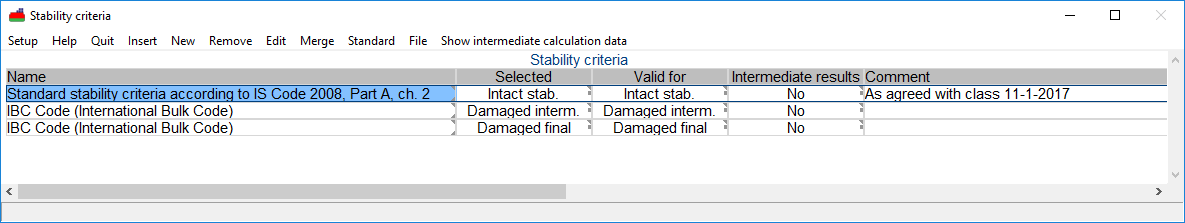
Choosing the stability criteria definition menu opens a window with the already defined sets of criteria, which will look like this:
Set of stability requirements.
With the <Enter> key (or mouse double click) one goes one level deeper into the stability criterion, where all specific parameters can be given. That menu is discussed in Manipulating individual criteria.
The columns have the following meaning:
- Name
The names of the different sets of criteria can be defined and altered by the user. In the example, one name appears twice; these are sets of criteria that are applicable to different calculations, but originate from the same regulations. The user could also define different names here.
- Selected
The different sets of criteria can be selected individually. This enables fast switching between different sets of criteria for the output of calculations. Upon selecting the cell in this column a popup menu will open up (from which an example is depicted below) which enables selecting a criterion set, for the types of calculations as defined in the column ‘Applicable for’.
- Valid for
This column shows the type of calculations to which a set of criteria applies. Changing the applicability of a set of calculations can be done through a popup menu, from which an example is depicted in the second figure below.
- Intermediate results
In this column, it can be specified whether the intermediate results of the calculated stability criteria should be generated. If these intermediate results are generated then these will be of the last made calculation. With each new calculation, the intermediate results of the previous one are removed.
This setting is only applicable within Loading when calculating intact and damaged stability and then exclusively for the following menus, Loading conditions and Define/edit weight items. This setting is also applicable for Hydrotables if in Hulldef it has been chosen to make use of a Drafts-displacements table.
The intermediate results can be viewed via the menu bar option [Show intermediate calculation data].
The intermediate results are written to the text file projectname.str that comes in the project folder, and can be opened with any text editor.
- Comment
- In this column the user can define additional comments.
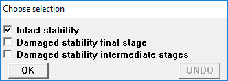
Selecting sets of criteria.
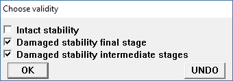
Choose applicability of criteria.
Furthermore, this menu contains a number of menu bar functions:
- With [Merge] two sets of criteria can be merged. This can sometimes prove to be handy when manipulating criteria sets, or in combination with import or export actions. The option [Merge] only works when one makes a copy of a set of criteria, through ‘Copy a row entirely’ see Copy, paste etc., which thereafter can be merged in any other set of criteria than itself.
- With option [Show intermediate calculation data] the intermediate results file will be opened in the standard text editor.
- With [Standard], standard stability criteria can be created, this is further discussed in Select standard stability criteria.
- [File] has two sub options: import and export, which can be applied to read or write a set of criteria from or to another PIAS criteria file. This option can, for example, be used to exchange a non-standard set of criteria with another project. When exporting, the selected criteria set — the one where the text cursor resides — is added to the specified file. On import a list of in the import file present criteria sets is displayed. From this list one can choose one criteria set which should actually be imported.
Select standard stability criteria
This function - activated by [Standard] in the window of criteria sets - will add a set of criteria to the already existing sets. Through popup menus a choice is made from the predefined sets of standard criteria for intact or damaged stability. First the choice for intact or damage stability criteria is made, as illustated in the figure below. Subsequenlty, depending on the choice, a popup menu with the available predefined sets of intact or damaged stability opens up, this will be discussed in the next sections.

Choice for intact or damage stability criteria.
Standard stability criteria intact stability
A number of standard stability requirements have been preprogrammed. Below is a list with references to the chapters with short references to the sources of the requirements in that chapter.
Seagoing
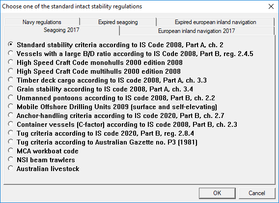
Standard criteria for intact stability, seagoing.
- Standard stability criteria according to IS Code 2008, Part A, ch.2
- Intact Stability Code 2008, almost identical to its predecessors IMO A.749 and IMO A.562.
- These regulations contain a subcriterion, stating that the statical angle due to wind may not be larger than 80% of the angle of deck immersion. Traditionally, and also today, PIAS determines this angle at Lpp/2. However, in 2006 it appeared that a regulatory body may require that the effect of trim is included. In that case the user will have to apply the variable ‘Angle of deck edge immersion’ instead of ‘Angle of deck immersion at L/2’ in this criterion.
- The Intact Stability Code also includes the so-called weather criterion, for which the roll data of the ship have to be specified, see for the definition menu Roll data (for Intact Stability Code weather criterion).
- Vessels with a large B/D ratio according to IS Code 2008, Part B, reg. 2.4.5
- This regulation is almost identical to the earlier mentioned Intact Stability Code standard stability criteria regulation but then with changes for the so-called ‘supply vessels’, meaning that the minimum angle of GZ-max will then be decreased to 15°, which will be compensated by a larger area under the GZ curve up to that angle. In accordance with reg. 2.4.5.2 of the IS Code.
- High Speed Craft Code monohulls 2000 edition 2008
- International Code of Safety for High-Speed Craft (2000), 2008 Edition, annex 8.
- High Speed Craft Code multihulls 2000 edition 2008
- International Code of Safety for High-Speed Craft (2000), 2008 Edition, annex 7.
- Timber deck cargo according to IS Code 2008, Part A, ch. 3.3
- Intact Stability (IS) Code 2008, Part A, chapter 3.3.
- Grain stability according to IS Code 2008, Part A, ch. 3.4
- Intact Stability (IS) Code 2008, Part A, chapter 3.4. Which is practiclly similar to, International Code for the Safe Carriage of Grain in Bulk, MSC.23(59), 1 January 1994. According to this Code the angles 12° and 40° should explicitly be included into the calculations. So, please take care that these angles are part of the range of heeling angles, as specified in Config.
- Unmanned pontoons according to IS Code 2008, Part B, ch. 2.2
- IS Code 2008, part B, chapter 2.2 or IMO A749(18) chapter 4.7, 4 nov 1993: Code on intact stability for all types of ships covered by IMO instruments.
- Mobile Offshore Drilling Units 2009 (surface and self-elevating)
- Code for the Construction and Equipment of Mobile Offshore Drilling Units, 2009 (MODU Code). Only surface and self-elevating.
- Anchor handling criteria according to IS Code 2020, Part B, ch. 2.7
- These Intact Stability Code 2020 criteria are similar to the ‘NMD 2007 & BV2014 anchor handling criteria’, seeExpired seagoing, albeit with the following two additions:
- The residual area between the righting lever curve and the heeling lever curve should not be less than 0.070 mrad.
- The maximum residual righting lever GZ between the righting lever curve and the heeling lever curve should be at least 0.2 meter.
- The IS Code also contains a requirement on minimum required freeboard aft (of 0.005L). This requirement is not included here, because it is no stability requirement, but a draft requirement instead, which can be given in the menu of main dimensions and further ship parameters (see Draft marks and allowable maximum and minimum drafts.
Just as with the NMD and BV criteria, a total load case (that is ship & anchor chain force) is tested here. With just the application of these criteria in a loading condition the maximum permissible anchor chain force is not determined, for that purpose module Maxchain, should be used.
- Container vessels (C-factor) according to IS Code 2008, Part B, ch. 2.3
- The criteria from the ‘Intact Stability Code 2008’ for container vessels greater than a 100 meter.
- Tug criteria according to IS Code 2020, Part B, reg. 2.8.4
- For ‘Intact Stability Code 2020’ tug criteria one or more choices might be applicable:
- Intact Stability Code 2020 (MSC 97-22-Add.1, 2.8.4.2 (self tripping))
- Intact Stability Code 2020 (MSC 97-22-Add.1, 2.8.4.3 (tow tripping))
- Tug criteria according to Australian Gazette no. P3 (1981)
- For ‘Australian Gazette no. P3 (1981)’ tug criteria one or more choices might be applicable:
- Australian Gazette no. P3 (1981), navigation area A, B or C
- Australian Gazette no. P3 (1981), navigation area D or E
- MCA workboat Code
- The Workboat Code Industry Working Group Technical Standard, June 2014, MS 183/01/23.
- NSI beam trawlers
- According to BadS 124/1977: 20% added to the standard criteria. Netherlands Shipping Inspection (NSI).
- Australian livestock
- Marine Order 43 (Cargo and cargo handling — livestock) 2006.
European inland navigation
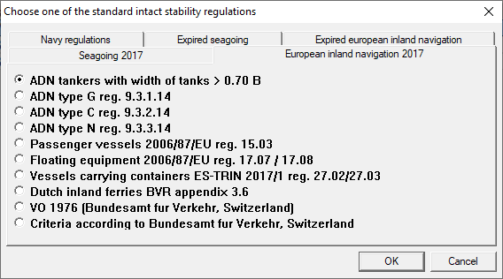
Standard criteria for intact stability, european inland navigation.
- ADN tankers with width of tanks > 0.70 B
- ADN, European Agreement concerning the International Carriage of Dangerous Goods by Inland Waterways, only applicable for:
- Type C tankers, reg. 9.3.2.14.2.
- Type N tankers, reg. 9.3.3.14.2.
- ADN type G reg. 9.3.1.14
- ADN, European Agreement concerning the International Carriage of Dangerous Goods by Inland Waterways, reg. 9.3.1.14.
- ADN type C reg. 9.3.2.14
- ADN, European Agreement concerning the International Carriage of Dangerous Goods by Inland Waterways, reg. 9.3.2.14.
- ADN type N reg. 9.3.3.14
- ADN, European Agreement concerning the International Carriage of Dangerous Goods by Inland Waterways, reg. 9.3.3.14.
- Passenger vessels ES-TRIN 19.03
- European Standard laying down Technical Requirements for Inland Navigation vessels, ES-TRIN 19.03.
- Floating equipment ES-TRIN 22.07/22.08
- European Standard laying down Technical Requirements for Inland Navigation vessels, ES-TRIN 22.07 and 22.08.
- Vessels carrying containers ES-TRIN 27.02/27.03
- European Standard laying down Technical Requirements for Inland Navigation vessels, ES-TRIN 27.02 and 27.03.
- Dutch inland ferries BVR appendix 3.6
- BVR (Binnenvaartregeling) 2009, Appendix 3.6.
- VO 1976 (Bundesamt fur Verkehr, Switzerland)
- Intact criteria according Bundesamt fur verkehr, Switzerland, Verordnung 1976.
- Criteria according to Bundesamt fur Verkehr, Switzerland
- Intact criteria according Bundesamt fur Verkehr, Switzerland.
Navy regulations
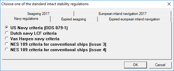
Standard criteria for intact stability, navy regulations.
- US Navy criteria (DDS 079-1)
- Specific criteria for American naval vessels.
- Dutch navy LCF criteria
- Specific criteria for some vessels of the Royal Netherlands Navy.
- Van Harpen navy criteria
- Stability criteria for the Royal Netherlands Navy according to Report Nr. 21183/21021/SB of the Ministry of Defence.
- NES 109 criteria for conventional ships (either ‘issue 3’ or ‘issue 4’).
- NES 109 issue 3 and 4. These criteria are very similar to those of BV, ‘Rules for the Classification of Naval Ships, Part B, chapter 3, section 2’. The differences are mainly in the applied criterion values.
Expired seagoing
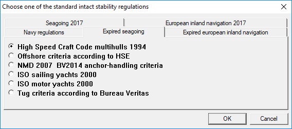
Standard criteria for intact stability, expired seagoing.
- High Speed Craft Code multihulls 1994
- International Code of Safety for High-Speed Craft. MSC.36(63), 20 May 1994.
- Offshore criteria according to HSE
- Criteria for offshore vessels according to HSE (DoE) and NMD.
- NMD 2007 & BV2014 anchor handling criteria
- These criteria evaluate a total load case (which is ship & anchor chain force) for compliance with NMD's Guidelines for immediate measures on supply ships and tugs that are used for anchor handling (2007). The anchor chain force should be defined acting at CL, because the NMD criteria require a certain ratio between the lever at the top of the GZ curve and the lever at the intersection between righting and heeling levers. In order for this ratio to appear, one should not include the heeling moment by placing the anchor chain force off centerline. So the chain force should be assumed to exert on the real chain position longitudinally and vertically, but always at center line. By the way, with only the application of these criteria the maximum permissible anchor chain force is not determined, for that purpose module Maxchain, should be used.
- ISO sailing yachts 2000
- ISO/DIS 12217, stability and buoyancy assessment and categorization, Part 2: Sailing boats of hull length greater than or equal to 6 m, 2000-10-05.
- ISO motor yachts 2000
- ISO/DIS 12217, stability and buoyancy assessment and categorization, Part 1: Non-sailing boats of 6 m length of hull and over, 2000-10-05.
- Tug criteria according to Bureau Veritas
- The tug criteria, of Bureau Veritas (D.14.2, reg. 2.2.2), have been replaced with the ‘Intact stability Code 2020’ criteria for self and tow tripping. In the Bureau Veritas regulations this can be found under, Part E, chapter 1, section 2, regulation 2.
Expired european inland navigation
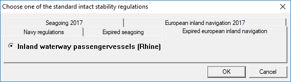
Standard criteria for intact stability, expired european inland navigation.
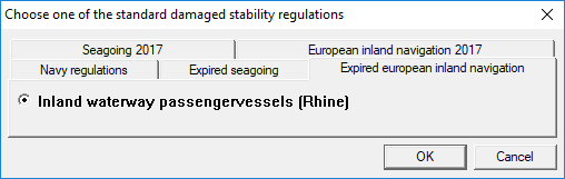
- Inland waterway passengervessels (Rhine)
According to Binnenschepenbesluit, Stbl. 466, or, alternatively, according to Bundesamt für Verkehr, Switzerland
Variants for standard sets of stability requirements
- Attention
- In the pre-2017 versions of PIAS, during the creation of standard intact stability criteria one would be asked the question to add other criteria, like tugs criteria, NSI interpretation and grain criteria or Australian livestock moment, to the to be created stability criteria. These choices are now integrated as standard criteria. When one for example wants to create intact criteria with grain criteria now has to create two standard sets of stability criteria, namely ‘Standard stability criteria according to IS Code 2008, Part A, ch. 2’ and ‘Grain stability according to IS Code 2008, Part A, ch. 3.4’ and then merge together them with the option [Merge], as discussed in Manipulating and selecting sets of stability criteria. From now on this the way to handle standard stability criteria where this is applicable.
For some standard sets of stability criteria, additional choices must be made. If so, a popup menu appears after selecting the standard set of criteria. Most of the options in these popup menus determine whether or not additional criteria are applicable and sometimes a value must be entered for a variable. For a description of the variables reference is made to Manipulating individual criteria and to Defining heeling moments to be accounted for. For other sets of standard criteria, an additional choice can be made, as shown in the example below. For the determination of such choices and requested values, reference is made to the relevant regulations.
Parameters ISO motor yachts.
Supplementary parameters tugs.
Supplementary parameters Dutch inland ferries BVR appendix 3.6.
Supplementary parameters SOLAS 2009.
Standard stability criteria damaged stability
These are, similar to the intact stability criteria, also presented in a popup window. Below is a reference list to the corresponding chapter which contains a table with short reference to the source of the regulations.
Seagoing
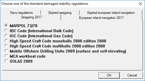
Sets of predefined criteria for damage stability, seagoing.
- MARPOL 73/78
- Marpol consolidated edition 2006.
- IBC Code (International Bulk Code)
- International Bulk Code 1998.
- IGC Code (International Gas Code)
- International Gas Code.
- High Speed Craft Code monohulls 2000 edition 2008
- International Code of Safety for High-Speed Craft (2000), 2008 Edition, annex 8. Note that the range can be reduced to 10 degrees if the area under the curve is increased by a factor of 15/range, see paragraph 2.1.1. Also note that these criteria make use of evacuation points which can be defined in Openings.
- High Speed Craft Code multihulls 2000 edition 2008
- International Code of Safety for High-Speed Craft (2000), 2008 Edition, annex 7.
- Mobile Offshore Drilling Units 2009 (surface and self-elevating)
- Criteria according MODU Code 2009, only surface and self-elevating. In article 3.4.1 it is stated that the range of stability has to be determined over the positive stability but that range is determined without the influence of the downflooding angle. In PIAS the downflooding angle is always used and also in this exceptional situation the downflooding angle has been taken into account. This is therefore in deviation with the stated regulations.
- MCA workboat Code
- The Workboat Code Industry Working Group Technical Standard, June 2014, MS 183/01/23.
- SOLAS 2009
- SOLAS 2009, Consolidated text 2014.
European inland navigation
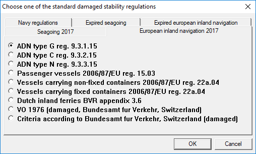
Sets of predefined criteria for damage stability, european inland navigation.
- ADN type G reg. 9.3.1.15
ADN, European Agreement concerning the International Carriage of Dangerous Goods by Inland Waterways, reg. 9.3.1.15.
- ADN type C reg. 9.3.2.15
ADN, European Agreement concerning the International Carriage of Dangerous Goods by Inland Waterways, reg. 9.3.2.15.
- ADN type N reg. 9.3.3.15
ADN, European Agreement concerning the International Carriage of Dangerous Goods by Inland Waterways, reg. 9.3.3.15.
- ADN container vessels (non-fixed containers) reg. 9.1.0.95
ADN, European Agreement concerning the International Carriage of Dangerous Goods by Inland Waterways, reg. 9.1.0.95.
- ADN container vessels (fixed containers) reg. 9.1.0.95
ADN, European Agreement concerning the International Carriage of Dangerous Goods by Inland Waterways, reg. 9.1.0.95.
- Passenger vessels ES-TRIN 19.03
European Standard laying down Technical Requirements for Inland Navigation vessels, ES-TRIN 19.03.
- Vessels longer than 110m with non-fixed containers ES-TRIN 28.03
European Standard laying down Technical Requirements for Inland Navigation vessels, ES-TRIN 28.03.
- Vessels longer than 110m ES-TRIN 28.03
European Standard laying down Technical Requirements for Inland Navigation vessels, ES-TRIN 28.03.
- Dutch inland ferries BVR appendix 3.6
BVR (Binnenvaartregeling) 2009, appendix 3.6.
- VO 1976 (damaged, Bundesamt fur Verkehr, Switzerland)
Damaged criteria according Bundesamt fur verkehr, Switzerland, Verordnung 1976.
- Criteria according to Bundesamt fur Verkehr, Switzerland (damaged)
- Damaged criteria according Bundesamt fur Verkehr, Switzerland.
Navy regulations
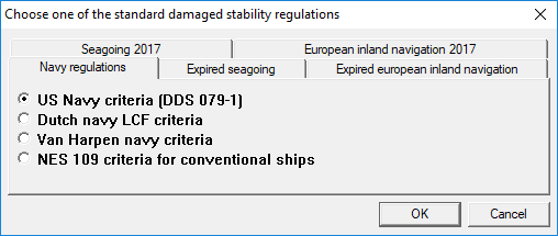
Sets of predefined criteria for damage stability, navy regulations.
- US Navy criteria (DDS 079-1)
- Specific criteria for American naval vessels.
- Dutch navy LCF criteria
- Specific criteria for Dutch naval vessels.
- Van Harpen navy criteria
- Stability criteria for the Royal Netherlands Navy according to Report Nr. 21183/21021/SB of Dutch Ministry of Defence.
- NES 109 criteria for conventional ships
- NES 109. These criteria are very similar to those of BV, ‘Rules for the Classification of Naval Ships, Part B, chapter 3, section 3’. The differences are mainly in the applied criterion values.
Expired seagoing
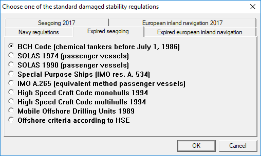
Sets of predefined criteria for damage stability, expired seagoing.
- BCH Code (chemical tankers before July 1, 1986)
- Code for the Construction and Equipment of Ships Carrying Dangerous Chemicals in Bulk, 1993.
- SOLAS 1974 (passenger vessels)
- SOLAS 1974.
- SOLAS 1990 (passenger vessels)
- SOLAS 1990.
- Special Purpose Ships (IMO res. A. 534)
- Special Purpose Ships Code IMO A.534.
- IMO A.265 (equivalent method passenger vessels)
- Regulation 5 of IMO A.265.
- High Speed Craft Code monohulls 1994
- Criteria according to HSC Code monohull passenger vessels 1994.
- High Speed Craft Code multihulls 1994
- Criteria according to HSC Code multihull passenger vessels 1994.
- Mobile Offshore Drilling Units 1989
- Criteria according to MODU Code 1989.
- Offshore criteria according to HSE
- Criteria for offshore vessels according to HSE (DoE) and NMD.
Expired european inland navigation
Sets of predefined criteria for damage stability, expired european inland navigation.
- Inland waterway passengervessels (Rhine)
According to Dutch Binnenschepenbesluit, Stbl. 466, or, alternatively according to Bundesamt für Verkehr, Switserland.
Manipulating individual criteria
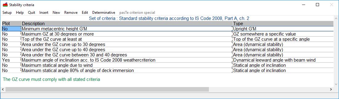
A set of criteria can be manipulated by selecting the set from the menu, Manipulating and selecting sets of stability criteria. This will open a menu with the individual criteria for this set:
Defining stability criteria.
Plot
For every individual criterion the user may choose to draw a GZ curve in the output. This is only useful for some types of criteria, such as a certain area under the curve or a static angle of inclination due to a (wind or other) heeling moment. In the tables of maximum allowable KG' values, no curves are drawn at all. If this option is not selected for any criterion, a GZ curve is still drawn in the output for the stability calculations for a loading condition, only without any hatching of areas etc.
Description
For each criterion a name can be given. This will be used in the output for identification purposes.
Types of basic criteria
- Attention
- The criteria as listed below include some where the other side of the GZ curve (i.e. left of the origin) play a role, such as ‘Area ratio windward / leeward’ en ‘Dynamical leeward angle with beam wind’. If the computation setting of Calculate intact stability etc. with a heeling to (and its relative for damage stability) is ‘Portside and starboard’, then the complete GZ curve from PS to SB is computed and available, so those stability criteria can be evaluated complete and correct. However, with any other setting the stability will be computed to just a single side, and will be mirrored to the other side — after all, no other information is available in this case. In case of asymmetrical hull forms or damage cases that might be less accurate than a full computation.
Basic types of criteria.
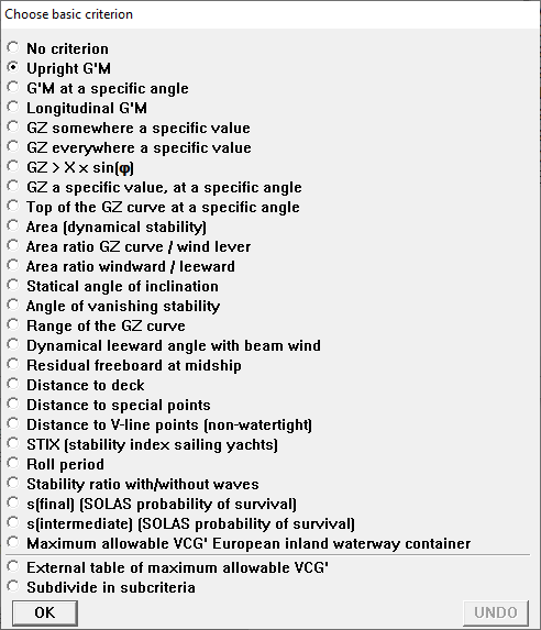
The available types of basic stability criteria can be selected from a popup menu. This menu appears when the user selects the cell. Each requirement can be set a number of variables. Everywhere in the list below where ‘a certain value’ is used, or similar words, it is meant that the value can be set freely by the user. An overview of the criteria per basic requirement is:
- No criterion
- No criterion is automatically selected for a newly added criterion, so that if a requirement is not explicitly defined, (including type), it will not influence the calculation.
- Upright G'M
- The G'M value at 0° must have a certain value. Here, upright, G'M is calculated with G'M = KM - (KG+GG'). In a calculation including the the shift of COGs of liquid (see (Damage-) stability including the shift of COGs of liquid), that GG' is determined using the free surface area of the liquid corresponding to the actual trim of the vessel. In a calculation without this setting, the basis for GG' is formed by the free liquid surfaces at even keel (zero trim). /dd>
- G'M at a specific angle
- The G'M at a certain (user=defined) angle of inclination is tested against a certain value. Here, as G'M the tangent to the GZ-curve at that angle of inclination angle is taken. There are three further explanations to be made to this criterion:
- The tangent to the GZ-curve may vary considerably in an area where teh GZ-curve has a large curvature. To be able to determine G'M accurately, in such areas a sufficient number of angles of inclinations (see therefore Angles of inclination for stability calculations) should be used (because the GZ-curve is formed by a calculation at those angles, inbetween is only interpolated).
- If the angle at which the G'M must be determined is zero, then the G'M according to this criterion is theoretically exactly the same as according to the criterion discussed just above. And practically also (provided there are sufficient angles if the curve in that neighborhood is rather curved).
- The comments made under Maximum allowable VCG at criterion `GM at equilibrium' also apply to this criterion.
- Longitudinal G'M
- The longitudinal G'M in upright position must have a certain value.
- GZ somewhere a specific value
- Within a certain range, the GZ value must be larger than a certain value somewhere.
- GZ everywhere a specific value
- Within a certain range, the GZ value must be larger than a certain value everywhere.
- GZ > X × sin(φ)
- Within a certain range, the GZ value must be larger than a certain value times the sinus of the angle of inclination somewhere.
- GZ a specific value, at a specific angle
- The GZ must be larger than a certain value at a certain angle.
- Top of the GZ curve at a specific angle
- The top of the GZ curve must lie beyond a certain angle.
- Area (dynamical stability)
- The area (in meter.radians) under the GZ curve must have a certain value in a certain range.
- Area ratio GZ curve / wind lever
- The ratio of the areas A ÷ B under the GZ curve and the wind lever respectively must have a certain value within in a certain range.
Area ratio GZ curve / wind lever.
- Area ratio windward / leeward
- The ratio of the areas A ÷ B enclosed by the GZ curve and the wind lever, calculated from a certain rollback angle windward,to a certain angle to lee must have a certain value.
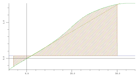
Area ratio windward / leeward.
- Statical angle of inclination
- The static angle of inclination must be less than a certain value.
- Angle of vanishing stability
- The angle of vanishing stability must have a certain value.
- Range of the GZ curve
- The range of the positive part of the GZ curve must have a certain value, within a certain range.
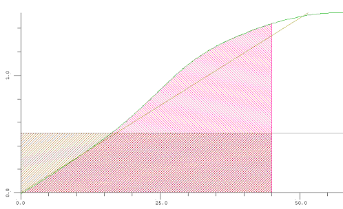
- Dynamical leeward angle with beam wind
- The roll angle to lee due to wind may have a certain maximum value, calculated from a certain rollback angle windward, with a certain factor for wind gust.
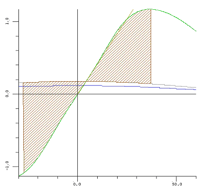
Dynamical leeward angle with beam wind.
The allowable angle leeward due to rolling under the influence of wind is assessed via the hatched surfaces. The area on the right side of the graph equals the area on the left side of the curve.
Note: The wind heeling lever is multiplied by a ‘wind gust factor’, see the differences in the wind heeling levers at Wind lever. Both levers are multiplied by the cosine of the heeling angle in the example.
- Residual freeboard at midship
- The remaining freeboard at half length (as determined from the depth and breadth in Hulldef) must have a certain value at the static angle of inclination.
- Distance to deck
- The distance from the waterline to the deckline (as determined from the depth and breadth in Hulldef) must have a certain value at the static angle of inclination.
- Distance to special points
- The distance from the waterline to openings or margin line points (as defined in Hulldef) must have a certain value at the static angle of inclination.
- Distance to V-line points (non-watertight)
- The distance from the waterline to V-line points (as defined in Hulldef, see Openings) must have a certain value at the static angle of inclination, with a certain roll margin.
- STIX (stability index sailing yachts)
- The coefficient according to the STIX requirement (as defined ISO/DIS 12217, from 2000-10-05) should have a certain value.
- Roll period
- The roll period as calculated from selected formulae must have a certain value. Available are estimations according to the Irish Maritime Authority (T = 0.7 × B ÷ √G'M), and those according to the Intact Stability Code.
- Stability ratio with/without waves
- The ratio of areas under the GZ curves for calm water and in waves may not exceed a certain value.
- s(final) (SOLAS probability of survival) and s(intermediate) (SOLAS probability of survival)
- The probability of survival should be greater than the given value. Applicable to passenger vessels, according to SOLAS 2009 and 2020, part B-1, regulation 8-2. Note that the ‘final’ criterion is subjected to the effects of evacuation points.
- External table of maximum allowable VCG'
- With this criterion the user can enter a table of maximum allowable VCG (or minimum required GM). For more details please refer to Input of externally defined tables of maximum allowable VCG'.
- Maximum allowable VCG' European inland waterway container
- The European ES-TRIN 2017/1 regulations contain rules, paragraphs 27.02 and 27.03, for the stability of (inland waterway) container vessels navigating the European inland waterways. These have been pre-programmed, and are readily available within PIAS, see Particulars for inland waterway container vessels for more information. In the end, these rules provide a maximum allowable VCG, which is used to assess stability where neccessary.
- Subdivide in subcriteria
- A criterion of this type can be defined as a set of criteria of all listed types. Such a set or subset of criteria can be treated, manipulated and defined as an independent set of criteria. It is even possible to create subsets within subsets.
Valid up to statical angle
This column is only valid for the criterion ‘External table of maximum allowable VCG' ’, because here it can be given to which statical angle of inclination this table is valid.
Determinative (toolbar function)
The toolbar function [Determinative] determines whether the most or least critical criterion is normative. In most cases all criteria should be complied with, in which case the bottom line in the window reads ‘The GZ curve must comply with all stated criteria’. However, it may occur that only one of the requirements needs to be complied with, which makes the bottom line to display ‘The GZ curve only needs to comply with 1 of the stated criteria’.
pasTe criterion special (toolbar function)
With the function [pasTe criterion special] one can copy one specific criterion from an other set of criteria to the current set of criteria. This function is only available when in a set of criteria other than itself with use of ‘Copy row’, see Copy, paste etc., a copy has been made of a criterion. This also means that this function will not be available when one uses the ‘Copy row’ in the ‘current’ set of criteria.
Defining the parameters of the stability criteria
For each individual criterion, all parameters can be defined. The type of criterion determines which value is checked, how this is done, etc. The general structure of the menu for defining the parameters per criterion is explained by the example of the wind criterion of the Intact Stability Code:
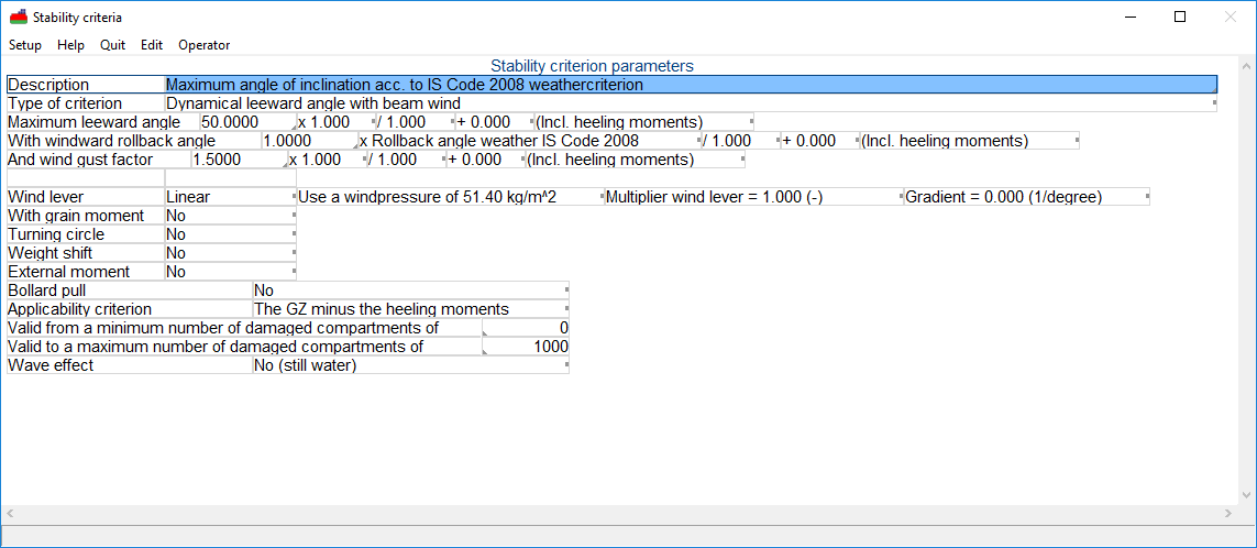
Example of definition per criterion.
Description
The first row contains the user-defined description, see also Manipulating individual criteria. The description can be changed through this menu.
Type
The second line contains the type of basic criterion as defined in the menu of Types of basic criteria. The type of criterion be changed in this menu with the exception of a few basic criterion such as, ‘No criterion’, ‘Subdivide in subcriteria’ and ‘External table of maximum allowable VCG' ’.
Parameters
Depending on the type of criterion, a number of rows containing the parameters for the concerning criterion follows. In this example there are three user-defined parameters: ‘Maximum leeward angle’, ‘With windward rollback angle’ and ‘And wind gust factor’. Setting these parameters is discussed extensively in The nature of the stability criterion parameters. An overview of possible parameters and their meaning is given in Types of parameters.
Moments
For each criterion different types of heeling moments can be accounted for (wind heeling moment, turning circle moment, etcetera). Depending on the type of moment, other settings may apply. Defining these moments and their settings is described in Defining heeling moments to be accounted for.
Bollard pull
At this option the trend of the heeling moment of the bollard pull, over the angles of inclination, can be specified. Possible choices are:
- No bollard pull
- Linear moment, so constant for all angles of inclination.
- Moment decreasing with the cosine of the angle of inclination.
- Austr. 1981 ABC: moment = bollard pull × (vertical lever × cos(φ) - breadth towing hook from CL × sin(φ)). By the way, this is the same formula as proposed in IMO SDC 3 (2015).
- Austr. 1981 DE: moment decreases according to the formula from the ‘Commonwealth of Australian Gazette no. P3 (May 11, 1981) sect 8, C10’: moment = bollard pull × (vertical lever x cos(φ+30) - breadth towing hook from CL × sin(φ+30).
- IS Code 2020, self tripping: according to, MSC 97-22-Add.1, 2.8.4.2. Which is the same formula as used by ‘Austr. 1981 ABC’.
- IS Code 2020, tow tripping: according to, MSC 97-22-Add.1, 2.8.4.3.
If applicable the bollard pull can be multiplied by a correction factor which can be entered at Towing hook and bollard pull. According to regulation, the correction factor is not applied for IS code 2020 tow tripping.
Furthermore, it can also be specified which vertical lever should be used to be multiplied with the bollard force, in order to obtain the heeling moment, with options:
- The distance between towing hook and the point halfway between draft and the virtual (keel) point, which can be specified with one of the hull definition modules (see Towing hook and bollard pull).
- The distance between towing hook and half the draft.
- The distance between towing hook and the COG of the lateral area, which will be computed from the underwater contour shape of the selected wind contour, for example Settings per loading condition.
- The distance between towing hook and any height from base. The height is defined in Towing hook and bollard pull as a virtual (keel) point.
- Attention
- For ‘IS Code 2020, tow tripping’ it is not possible to specify a vertical lever because it can not be applied in the formula in a standard way.
Applicability of the criterion
For each criterion the GZ curve it can be specified whether the criterion should be applied on the ‘The GZ minus the heeling moments’, or the ‘The GZ curve only’.
Wave effect
Some criteria may be applicable to the vessel in a wave. The way to account for a wave can be defined through a popup menu;
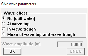
Wave properties.
If a wave top or wave trough is selected, the amplitude must also be specified (on the same row). The GZ curve is then calculated for this criterion with the vessel in a wave with the defined amplitude and a wave length of twice the vessel length, with the wave top, respectively the through at half the vessel's length.
If the mean of wave top and trough is selected, the GZ curve is calculated twice (for a wave top and a wave trough) and for each angle of inclination, the average GZ value is calculated. The criterion is then evaluated for the GZ curve constructed in the described way.
The nature of the stability criterion parameters
- Attention
- It is advised to study this section thoroughly to avoid misunderstandings. Especially due to the way parameters can be defined, as described in this section, checking stability criteria has become extremely flexible in PIAS. Unfortunately, the increased freedom involves increased complexity. Therefore, read the manual carefully in general and this section in particular
Types of parameters
This section describes the possible parameters that can be defined depending on the type of basic requirement. Parameter here means: the quantity appearing in the left column, in the rows directly under the ‘Type of criterion’, see picture below the title of Defining the parameters of the stability criteria.
- Between start angle
- Start angle of the range in which a parameter must reach a certain value. [degrees].
- And end angle
- Final angle of the range in which a parameter must reach a certain value. [degrees].
- Metacentric height
- Inclination of the tangent of the GZ curve. [m/rad].
- At angle
- The angle at which a parameter must reach a certain value. [degrees].
- Longitudinal metacentric height
- Metacentric height in longitudinal sense. [m].
- Righting lever
- Righting moment divided by displacement. [m].
- The value for X
- Factor x for a basic requirement in which the key parameter varies, for example with the angle of inclination, in the type of basic criterion: GZ > X × sin(φ). In this example: [m].
- Angle of maximum GZ
- The angle belonging to the maximum GZ value. [degrees].
- Area
- Area under the GZ curve. [mrad].
- Area ratio
- Ratio of areas under GZ curves or GZ curve and a wind heeling lever curve. [-].
- To angle
- To which angle from the statical angle must be rolled. [degrees].
- Rollback angle windward
- The rollback angle from the statical angle. [degrees].
- Statical angle of inclination
- Static angle of inclination at equilibrium (For damage stability at belonging stage of flooding). [degrees].
- Angle of vanishing stability
- The angle beyond which the GZ becomes negative or the angle at which the open openings submerse if that is smaller. [degrees].
- Range of the GZ curve
- Range for the positive part of the GZ curve. [degrees].
- Maximum leeward angle
- Allowable angle to lee for assessment of the dynamic wind heeling. [degrees].
- With windward rollback angle
- Angle windward for assessment of the dynamic wind heeling. [degrees].
- And wind gust factor
- Multiplier for wind heeling lever due to constant wind pressure, to account for a wind gust for assessment of the dynamic wind heeling. [-].
- Residual freeboard at midship
- Freeboard at 1/2 Lpp at the static angle of inclination. [m].
- Distance to deck
- Required distance from the waterline to the defined deck line points (see Deck line). [m].
- Only outside damaged region
- The deck line or other points within the length of the damaged part (to be defined in the appropriate module for damage stability) will be taken into consideration, depending on the choice made here. [-].
- Only applicable to deck at centerline
- Defined points are considered at the defined breadth or at breadth=0, depending on the choice made here. [-].
- Distance to special point
- Required distance from the waterline to the defined special points (as defined at ‘openings’ in Hulldef). [m].
- Type of special point
- The type of special point for which this requirement is applicable can be selected here. [-].
- Emergency exits to be included
- Is specific for the special point type emergency exit. This specifies how emergency exits are to be taken into account. There are two ways how these are taken into account:
- All emergency exits are taken into account in the calculation.
- An emergency exit in the sense of the ADN criteria. Meaning that, when multiple emergency exits have been connected to a compartment that in the final stage one of those emergency exits should stay above the waterline with a minimum distance of 0.100 meter.
- Distance to waterline
- Normally a special point is compliant if its distance is greater than the required distance from the waterline, i.e. Minimum. For the special point of type margin line, the Maximum can also be taken. This means that the calculated distance is smaller than the required distance from the waterline.
- Distance to V-line points (non-watertight)
- Required distance from the waterline to the defined special points (as defined at ‘openings’ in Hulldef). [m].
- Roll margin
- Increase of static heeling angle, for which the V-line points must have the defined distance to the waterline. [degrees].
- From angle of inclination
- Start angle of roll, only applicable for navy vessels with Vline points. [degrees].
- Stability index STIX
- Required value for the stability index. [-].
- Roll period
- Required roll period. [s].
- Estimation method
- Option for choosing the estimation method for the roll period. [-].
- Stability ratio
- Ratio of the areas under the curves for still water and in waves. [-].
- Angle for determination of area
- The angle to which the area will be determined, according to NES 109, Issue 3. [degrees].
- Probability of survival s(final) and Probability of survival s(intermediate)
- The required probability of survival s, according SOLAS 2009 for passengervessels and in case of s(final) taking into account evacuation points. [-].
- Ship type
- In SOLAS 2009 s(final) contains a choice for the type of vessel. [-].
- Transport of containers
- If the calculation is to be made for secured or non-secured containers. Please note, when changing this parameter that it is advised to modify the description of the criterion to reflect the current state of the parameter. [-].
- Calculation method
The method to be used for calculating the maximum allowable VCG according ES-TRIN 2017/1 reg. 27.02/27.03 [-].
The following methods are available:
- Approximation formulae, based on the formulaes for maximum allowable VCG, as described in the second article.
- Direct calculation, based on basic PIAS criteria as described in the first article of the afore mentioned regulations. This calculation is based on the calculated GZ-curve and curves for heeling moments. This calculation is more accurate.
Variables
This section describes how to define the appropriate values for each parameter. Each row contains four user-defined variables. The first one is always a user-defined number. The remaining three parameters can be either user-defined values or calculation results, see below. Some parameters can be evaluated either for the GZ curve, corrected for heeling moments (including heeling moments) or for the uncorrected GZ curve (excluding heeling moments). This setting has no effect if no heeling moments are defined for the concerning criterion. Defining the remaining three parameters is done by means of a popup menu:
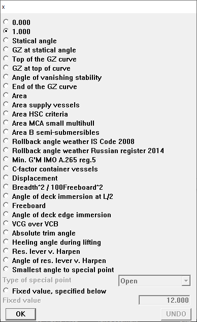
Parameters for stability criteria.
If one of the parameters is selected, the corresponding value is used during evaluation of the concerning criterion. These variables are:
- Statical angle
- Statical angle at equilibrium.
- GZ at statical angle
- GZ value at angle of equilibrium (in case of defined moments).
- Top of the GZ curve
- Angle for which the largest value for GZ occurs.
- GZ at top curve
- Largest GZ value.
- Angle of vanishing stability
- Angle for which the GZ becomes negative.
- End of the GZ curve
- Largest of the calculated (defined) angles that the GZ is calculated for.
- Area
- Total area under the positive part of the GZ curve.
- Area supply vessels
- The required area under the curve for vessels with a large B/H ratio (alternative criteria according to the Intact Stability Code) = 0.055 + 0.001 × (30-angle at which the maximum GZ occurs).
- Area HSC criteria
- The required area under the curve according to ‘High Speed Craft Code 2000 edition 2008’ = 0.055 × 30 ÷ minumum(downflooding angle, angle of maximum GZ, 30 degrees).
- Area MCA small multihull
- The required area under the curve according to the MCA small multihull rule (MCA brown Code, §11.1.2.6.1) = 0.055 + 0.002 x (30-angle at which the maximum GZ occurs).
- Area B semi-submersibles
- The required area B for semisubs. However, this function has not yet been implemented.
- Rollback angle weather Intact Stability Code 2008
- The rolling angle windward as defined in the Intact Stability Code. For application of this parameter, please verify that in the Hulldef module the correct properties are defined at the applied wind contour (such as bilge shape and bilge keel area).
- Rollback angle weather Russian Register 2014
- According to part IV, regulation 2.1.5 of the Rules for the Classification and Construction of Sea-Going Ships from the Russian Maritime Register of Shipping, 2014. This rollback angle is virtually identical to that of the Intact Stability Code, there is a small difference in the X1 factor, which is given for a somewhat larger range of B/d. Furthermore, there is an exception for dredgers in regulation 3.8.4.3, which is the correction factor X3 for the windward rollback angle in case of a restricted area of navigation. If at the definition of a stability requirement a specific wind pressure is set (see Wind lever for that) of less than 51.4 kg/m2, then the navigation area is assumed to be restricted, and hence the X3 applies. It is possible to verify whether X3 has been applied by inspection of the intermediate results, because there it will be printed if applicable.
- Min. G'M IMO A.265 reg. 5
- The minimum G'M based upon, IMO A.265 regulation 5.
- C-factor container vessels
- C factor for container vessels according to the Intact Stability Code. For this factor the vessel should be defined including hatch coaming (if present).
- Displacement
- Displacement (in intact condition).
- Breadth^2 / 100Freeboard^2
- Breadth 2 ÷ (100 × freeboard 2). Obviously, the depth should have been correctly defined in Hulldef.
- Angle of deck immersion at L/2
- The angle where the deck at Lpp/2 is immersed. This function does neither apply to the geometry of the vessel, nor to the defined deck line. It is simply based on the depth, as specified with the main dimensions.
- Freeboard
- Depth - draft. This value is calculated with the depth as defined in Hulldef.
- Angle of deck edge immersion
- The angle at which one of the deck line points, as defined in Hulldef, is immersed.
- VCG over VCB
- VCG - VCB for zero inclination.
- Absolute trim angle
- The absolute trim angle in degrees, see On the various criteria and parameters an application.
- Heeling angle during lifting
- By ‘loss of load’ calculations this variable is filled with the heeling angle during lifting in degrees. This variable is 1 in every other situation.
- Optimal start angle range IBC/IGC
- The optimal start angle of the range, according regulation 2.7.2.1 of the International Gas Code, 2016, MSC.370(93)
- Smallest angle to special point
- The first special point of the selected special points, as defined in Hulldef, to be immersed.
- Res. lever v. Harpen
- The remaining GZ according to formulae as defined by Van Harpen.
- Angle of res. lever v. Harpen
- Angle for which the residual lever according to Van Harpen occurs.
Operators
For each parameter the operator (the calculation to be performed) can be chosen. Choosing the operator is done via the toolbar option [Operator], if the concerning parameter is selected. A popup menu will then appear:
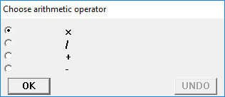
Selecting arithmetic operators.
- Attention
- The conventional order of arithmetic does not apply to the use of these operators. The order in which the operators are evaluated is simply from left to right.
Defining heeling moments to be accounted for
The heeling moments to be included in the calculations can be evaluated separately or combined. If multiple heeling moments are defined for a criterion, the GZ curve can be corrected (if necessary) for the total of heeling moments.
Wind lever
Selecting the way in which the wind levers are evaluated is done in a popup menu:
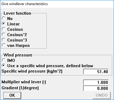
Selecting type of wind lever.
As depicted in the figure above, six types of wind lever functions are predefined:
- None.
- Linear, a straight line. Here also the gradient can be given, which is the inclination of the straight line. With a gradient of zero there is no inclination, which makes the wind lever to be constant for all angles of inclination. If a gradient is given, the wind lever is multiplied by the factor (1 + angle × gradient). Assume that for an angle of 40° the wind lever should amount 80% of the lever at 0° , then a gradient of -0.005 should be given.
- Cosine shaped, where the wind lever decreases with the cosine of the angle of inclination.
- Cosine squared, where the wind lever decreases with the square of the cosine of the angle of inclination.
- Cosine cube, where the wind lever decreases with the cube of the cosine of the angle of inclination.
- Van Harpen, where the wind lever follows van Harpens formulae (0.25 + 0.75 × cos(angle of inclination)3).
If a wind lever is present the user also should also either select one of the predefined wind pressures (as defined in the Hulldef module, at the wind data section), or give a specific wind pressure, in in kg/m2. Alternatively, a specific wind pressure in kg/m2 can be directly specified. The background of this parameters is discussed under lemma ‘specific wind pressure’ in Input data for the wind heeling moments computations.
In addition, a multiplier for the set wind lever can be specified. This parameter is also discussed in the just mentioned section, under the lemma ‘multiplier on the wind lever’.
Grain heeling lever
When for the concerning criterion a grain-heeling lever is defined, this option includes or excludes it in the calculation results for this criterion.
Turning circle
If this option is selected, a heeling lever due to the centrifugal force in a turning circle is applied. The lever is given by the user as a dimensionless constant, which is multiplied by the program by (KG - T/2) in order to obtain the turning circle lever for the loading condition concerned (and by displacement × (KG - T/2) to obtain the turning circle moment in tonmeter). In general, the heeling lever of the turning circle moment decreases with the cosine of the heeling angle, however, that still has to be set by the user (leaving the freedom to choose another function, such as linear).
Shift of weight
A shift of a weight can be included for evaluation of a criterion. Both weight and dislocation can be defined. The GZ curve will be calculated including the effect of the dislocated weight.
External heeling moment
An external heeling moment can be included. The magnitude of this moment can be defined, and the behavior of this moment can be selected, similar to the wind lever, see Wind lever.
Whether or not to apply heeling moments
It has already been discussed that in two occasions it can be specified whether or not to apply the heeling moments:
- For each individual variable, as used to compute the value of a parameter. This is specified with the cell ‘Incl. heeling moments’ or ‘Excl. heeling moments’.
- For the entire criterion, at the field ‘Applicability criterion’, where ‘The GZ curve only’ or ‘The GZ minus the heeling moments’ can be entered.
These two configurations have a distinct application. The first is valid for the line on which it occurs only, and determines whether the actual value of the variable should be determined including or excluding the heeling moment effect. If, for example, in a line the variable ‘Statical angle’ is used, this configuration determines whether this is the statical angle determined with or without heeling moments.
The second configuration applies to the entire criterion, and determines whether it should be applied on the GZ curve only, or on the GZ curve corrected for heeling moments. Suppose a criterion requires a minimum value for the maximum GZ, than this criterion s such is not related to any heeling moment (regardless whether the criterion value should be derived taking heeling moments into account), so it is applied on the GZ curve only. However, should the criterion require a minimum lever between GZ curve and heeling moment instead, then it is applied on the GZ curve minus the heeling moment.
Input of externally defined tables of maximum allowable VCG'
One particular type of basic criterion, as discussed in Types of basic criteria, is the external table of maximum allowable VCG'. This criterion can, for example, be used to process maximum allowable VCG's as determined for the probabilistic damage stability, with the Probdam module, in tables or diagrams — or in the LOCOPIAS on-board loading software. These tables can be defined for multiple trims, while multiple sets of tables can be defined. Only the selected set is used for the determination of maximum allowable VCG'. Maximum VCG's for intermediate values are determined by linear interpolation. Please keep in mind that for probabilistic damage stability according to SOLAS-2009 the VCG' between the three standard drafts - light, partial and deepest - must be determined by linear interpolation on G'M. So, in this case these values must be defined at this option as G'M values.
Settings of external table of maximum allowable VCG'
In the toolbar of the external table sits an option [Settings] where several settings with regard to the whole table can be modified.
- G'M or VCG'
- That at the drafts the defined values are interpreted as G'M or VCG'.
- Outside bounds valid
- If this is not turned on, then in case of drafts or trims outside the defined boundaries, the stability will be assessed as insufficient. In the situation that it is turned on, then for the drafts or trims which are outside the defined boundaries, the nearest values are used. So, there will be no extrapolation outside the defined range.
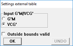
Settings external table.
Answers to frequently asked questions on stability assessments
The effect of openings
All basic requirements take implicitly and irrevocably into account the non-watertight openings: weathertight openings may not be submersed at the static angle of inclination. Beyond the angle of submersion of open openings the curve is terminated, so the GZ in that range is not taken into account when evaluating a requirement.
Seemingly inconsistency in weather criterion from the Intact Stability Code
If the criterion ‘Maximum angle in weather criterion Intact Stability Code’ is the determining one, it is possible that although in the summary of a loading condition the maximum allowable VCG is less than the actual VCG', the program reports that the loading condition complies. This effect is caused by the formula for determining the ‘Roll angle windward’ in which the uncorrected VCG (that means, uncorrected for free surface effects) must be applied, and this value might in a real loading condition differ from the assumption for determining the maximum allowable VCG (where there is obviously no separation between real and virtually risen VCG).
Determining parameter in the weather criterion from the Intact Stability Code
According to the text of the Intact Stability Code (IS) the ultimate parameter that determines whether the wind criterion is met, is the surface on the right side of the GZ curve b, which should be larger than that on the left, a. PIAS uses a slightly different parameter: b is set equal to a, and the roll angle is determined at which this is exactly the case. This angle may not exceed the maximum — usually 50°, or when an opening is submerged. This presentation is a bit more appealing for a human than the IS view, because inclination angles are a more intuitive notion than some area under a GZ curve. Obviously, eventually the conclusion is exactly the same.
Extent for determining the minimum lever of the area under the stability curve.
Some damage stability requirements have been nicely conceptualized, but may turn out a bit unexpected in practice. For example the requirement that ‘within a range of 20° from the statical angle of inclination’ a minimum area or lever should be present. Take for example the case depicted in the figure below, which shows two GZ curves. The red one is evidently better than the green one, because of its larger area and smaller statical angle of inclination. However, the ‘within a range of 20°’ plays foul, because the statical angle is A, which makes ‘plus 20°’ to be situated at C. And because of the flat character of the GZ in that region the area is small, too small to fulfill the minimum requirement. With the green curve the statical angle is B, which ‘plus 20°’r leads to D, resulting in a much larger area. The result is that the better GZ curve does not comply, while the worse does.
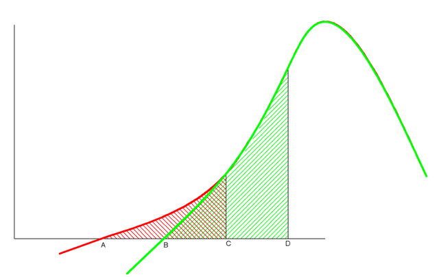
Two curves of righting levers in damaged condition.
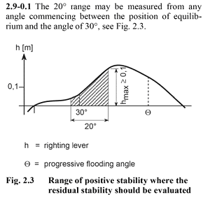
As such, this finding is not new, at SARC this phenomenon appeared in 1989 for the first time. And the solution is simple, by not taking this 20° from the statical angle of inclination, but from any angle between the statical inclination and the maximum allowable inclination instead. In PIAS this is achieved by subdividing this kind of criteria in many (more than ten) sub-criteria which each cover a piece of the search area, and taking the best. For the legislator this is also charted waters, as illustrated by the text of MSC/Circular.406/Rev.1 — Guidelines on Interpretation of the IBC Code and the IGC Code — (adopted on 29 June 1990), which reads: ‘....The 20° range may be measured from any angle commencing between the position of equilibrium and the angle of 25°....’. Also classification societies might be aware of this effect, given the figure below with an interpretation by Germanischer Lloyd. However, it is never guaranteed that this position is recognized in all cases, so it is advised to inquire in advance.
Interpretation of GL for the calculation of the area under the GZ curve with the IGC Code.
Maximum allowable VCG at criterion `GM at equilibrium'
An occasional stability regulation contains a criterion of ‘G'M at equilibrium’, so, at the statical angle of inclination. However, for this criterion multiple solutions may be possible, in other words, multiple KG's where G'M exactly matches the criterion value. Moreover, in general an increasing KG' will be detrimental for stability, but for this criterion this need to be not so: with the rise of K'G, in an asymmetrical damage case, the equilibrium angle will increase, so it may shift to a steeper part of the GZ curve. Where the G'M is larger, and this criterion is better matched! The general assumption is that a diagram of maximum allowable KG' contains a single transition line between areas of sufficient and insufficient stability, but with this particular criterion this does not hold because the diagram can contain islands of sufficiency or insufficiency. The search procedure of PIAS will find a single transition KG', but there may be more.
On the various criteria and parameters
This manual describes all functionality regarding the (damage) stability criteria. However, in the PIAS implementation a segregation into three ‘packages’ is applied:
- Standard (item 50.200.10 of the price list).
- Naval criteria (50.200.30), everything related to ‘naval’, such as DDS-079, van Harpen and NES-109.
- Extensions 2009 (50.200.40):
- Incorporation of the bollard pull moment into the stability analysis.
- Stability criteria for tugs, according to Bureau Veritas (2006). Will be superseded by Intact stability Code 2020 self and tow tripping.
- Stability criteria for tugs, according to the Commonwealth of Australian Gazette no. P3 (11 mei 1981) sect 8, C10.
- The parameter Absolute trim angle, to accomodate the combined heel and trim, as required by chapter 17.07 of the ROSR (vessels on the river Rhine).
- The parameter Area MCA small multihull. This is similar to the required area for supply vessels, but with a small difference: 0.055 + 0.002 × (30-angle at which maximum GZ occurs) instead of 0.055 + 0.001 x (angle at which maximum GZ occurs). Is applied in the MCA small boat Code (brown Code) for multihull vessels (§ 11.1.2.6.1).
- Extensions 2017 (50.200.50):
- Bollard pull function ‘Self tripping’ according to, Intact stability Code 2020 (MSC 97-22-Add.1, 2.8.4.2).
- Bollard pull function ‘Tow tripping’ according to, Intact stability Code 2020 (MSC 97-22-Add.1, 2.8.4.3).
- The basic criterium ‘s(final) (probability of survival) and s(intermediate) (probability of survival)’ and parameter ‘Probability of survival s(final) and Probability of survival s(intermediate)’ for SOLAS 2009, with regard to passenger vessels, according to Consolidated text 2014, part B-1, regulation 8-2.
Finally, on the completeness of the stability criteria the following disclaimer statements are made:
- The sets of predefined standard criteria do not offer a complete and up-to-date survey of all stability criteria. The user should always check the applicable stability criteria with the authorities concerned.
- Because criteria are often prone to interpretation, users must check for themselves that the requirements are defined according to the prevailing interpretation. Users are able to change selected predefined sets of criteria to meet their own interpretation.
- A consequence of the flexibility of the system is that it is not possible to check whether input data are realistic or even possible. It is, for instance, possible to define contradictory criteria. PIAS users are expected to be capable to investigate whether a certain criterion yields the correct results.
- It is recommended to generate and check intermediate results in case of unclear or unexpected results.