|
PIAS Manual
2026
Program for the Integral Approach of Shipdesign
|
|
PIAS Manual
2026
Program for the Integral Approach of Shipdesign
|
The main purpose of the wireframe functionality in Fairway is the import of 3D curves from a different source than Fairway — e.g. from a general-purpose CAD-system such as Autocad or Rhino — and their conversion to a Fairway model. The global procedure of this process will be discussed in The entire procedure to import DXF or IGES files.
Having this functionality in Fairway also serves a secondary purpose, which is that a design which starts with a ‘blank sheet’ (a so-called ab initio design) can be set up sketch-wise with initially unconnected curves. At some point this wireframe will need to be converted into a solid though, which comes with its own set of challenges and requires an advanced understanding of topology and geometry.
Finally, a third application of loose points and curves is in the support of the design of another solid, such as the marking of important positions, construction lines and as the master in master/slave relations.
IGES and DXF are popular file formats, and support for these formats is an important feature. However, DXF and IGES are not particularly suitable for the exchange of ship hull forms. One must keep in mind that these two formats are essentially intended for drawing exchange, and not for the exchange of product model data, an aspect which is confirmed by the full names of the acronyms (DXF: Drawing eXchange Format, IGES: Initial Graphics Exchange Specification). Unfortunately, this background inhibits a guaranteed error-free, automatic import of hullforms as proper Fairway solids for every case. That is why IGES and DXF files are imported as a wireframe, after which they can be made suitable for conversion to solid within Fairway.
Import of lines from a 3-D DXF is started with the corresponding option in the start menu. The following menu appears:
A 3-D DXF file contains dimensionless coordinates in an XYZ system of axes. So before the import can start the correspondence between DXF's XYZ coordinate system and the longitudinal, transverse and vertical axes of the ship must be specified. In addition, a multiplication factor must be given that will be applied on all DXF coordinates (for instance 0.001 when the DXF data are in millimetres).
Options 5 and 7–9 — from which the backgrounds are discussed in Intermezzo on polylines — are palliatives to deal with badly constructed DXF files. If possible, it can be a better idea to instruct the exporting computer program to structure its output in a more appropriate way. DXF supports geometric elements of quite a number of different types, of which Fairway supports the following:
POLYLINE and LWPOLYLINE. With these types a curved line is approximated by a chain of many small straight lines. A property of this representation is that knuckle points are not defined explicitly (because theoretically each point is a knuckle). So knuckles have to be added artificially. This can be done automatically during the import according to the criteria of options 7–9, or manually in Fairway. Polylines are converted into polycurves that are faired through all points of the polyline, which can result in an unnecessarily large number of points per curve.LINE. This is simply a straight line between two points. Sometimes this type occurs inappropriately often in a DXF file, where another type would should have been used. An example is when all elements of what actually is a polyline are transferred as LINE elements. With option 5 switched on Fairway will merge successive lines (within a tolerance of 0.1 mm) to larger polylines regardless. If this option is off, import of a large number of lines will result in Fairway in a great number of unconnected short polycurves that tediously must be merged into longer curves and polycurves.ARC. A circular ARC.SPLINE. Actually this is a NURBS curve. A property of this representation is that multiple segments that together represent a continuous polycurve, are not connected in DXF and therefore most be connected in Fairway later on. Again, option 5 will do its best to merge successive curves automatically. Another aspect of this type of elements is that, although the geometry is transferred exactly, no internal points exist. Consequentially, if these curves are faired in Fairway prior to the insertion of a sufficient number of points, a lot of detail can get lost.It is a sad experience that more often than not only a model without explicit information about the knuckles is available. For those occasions the import procedure is equipped with auxiliary functions, which may help to create knuckle points automatically. However, it must be emphasized that those functions are only palliatives, and are in no respect a replacement for proper definition of knuckles in the input data. These functions come in four flavours:
Regardless of the data carrier (DXF or IGES), NURBS curves are to be preferred above polylines. The reason is that Fairway converts polylines to NURBS anyway, and that conversion may always lead to a reduced accuracy.
Import of lines from a 3-D IGES file is started with the corresponding option in the start menu. The following form appears, described below.
A 3-D IGES file contains dimensionless coordinates in an XYZ system of axes. So before the import can start, the correspondence between IGES' XYZ coordinate system and the longitudinal, transverse and vertical axes of the ship must be specified. Option [Merge succeeding curves] has been discussed as first auxiliary function in the intermezzo just above.
IGES supports a large number of geometric entities. Fairway recognizes these entities:
SARC has defined an open file format that supports Fairway's polycurves and solid definitions to enable third parties to exchange models without the dependence on assumptions and heuristics. A model in this format consists of two files: the curve and polycurve definitions are in a text file with extension .cxf and the solid definition is in a text file with extension .sxf. The format of these files is discussed in the appendix, see File CXF and SXF file formats.
For applications that must frequently export their hull forms to Fairway, it is recommended to develop an interface routine that writes CXF and SXF files directly. With this file combination there is no need for Fairway to reconstruct the shape of the solid, thus saving time and avoiding possible reconstruction anomalies. In this way, also external applications — e.g. for the generation of parametric objects, such as cilinders, gas tanks, NACA profiles, keels and rudders — can store their shapes in a fashion that enables smooth import into Fairway.
Normally, functionality for working with wireframes is disabled in the user interface of Fairway, in order not to confuse the user with options that would not be applicable. Therefore, if one wants to set up a wireframe by hand, this functionality needs to be enabled in [Fairway project settings], option [Enable wireframe modeling]. When a wireframe is imported then this option will be enabled automatically.
Hereafter it is possible to add a new empty wireframe in [Object management]. In case a project needs no solids at all, the last option in the start menu is appropriate: [Start with empty model (advanced)].
New free polycurves can be added to a wireframe by connecting points using the action [Connect Points]. Points can be added using the action [Wireframe points]. For further wireframe manipulations consult Actions for wireframe manipulation.
A wireframe model is an open approximation of a solid, constituted by edges and vertices (`vertices' is the plural of `vertex') on the boundary of the solid. For example, the object in the figure below contains 4 vertices and 6 edges. However, because the wireframe model does not describe the closed object it is ambiguous. A proper unambiguous way to describe a solid object is the method of boundary modelling, where explicit information about the faces is included in a so-called boundary representation, or B-rep. Our example below contains four faces.
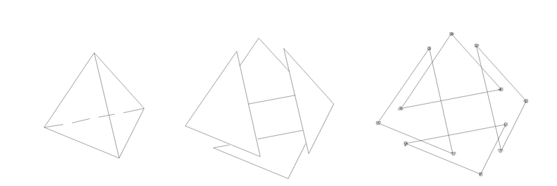
There is a well-known relationship between the number of vertices (V), edges (E) and faces (F); for solids without trough-holes this so-called Euler relation is V-E+F=2. It can be verified easily that this relation is indeed applicable on the figure above.
The necessity of explicit face information to describe a solid unambiguously can be demonstrated with the object in the figure below. With wireframe information only (vertices and edges) the actual shape of the object cannot be determined.
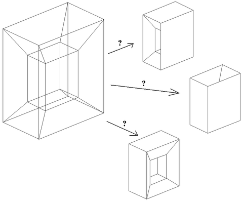
So an important task in the conversion of a wireframe to a solid is the recognition of the faces between the edges. In general, this problem is unsolvable, but under some practical constraints iterative methods are available. One of those methods is implemented in Fairway. This method implies the following constraints:
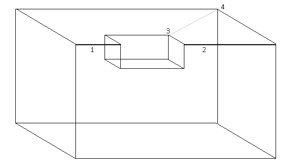
A 2-connected solid is a solid where the removal of 2 vertices separates the solid in two parts. For example, the object in the figure below is 2-connected, because the removal of vertices 1 and 2 leaves the small inner part unconnected from the larger, outer part. By the way, one additional edge between the vertices 3 and 4 would make this object not 2-connected anymore.
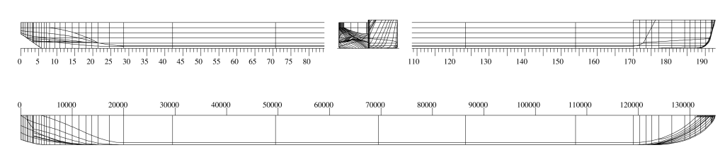
One might perhaps expect at first sight that this freak object is unlikely te be encountered when importing ship's lines. However, consider a very simple initial body plan in the figure below. This one is highly 2-connected, because many combinations of edges exist which leaves the object separated at deletion (edges 2-4 & 3-5, 4-6 & 5-7, 6-8 & 7-9 etc.).
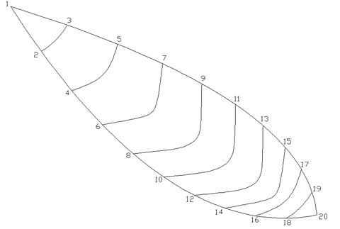
A few more remarks can be made about this figure:
It would lead us too far to discuss all theoretical aspects, but fortunately there are some exceptions where 2-connectivity is allowed:
All these considerations have led to a two-stage face recognition procedure in Fairway:
If wireframe modeling is enabled (see [Fairway project settings]) then the user has access to the following dedicated actions:
Further, the following generic actions also work on wireframe curves: