|
PIAS Manual
2026
Program for the Integral Approach of Shipdesign
|
|
PIAS Manual
2026
Program for the Integral Approach of Shipdesign
|
This PIAS manual is not the proper place for an in-depth explanation of the probabilistic damage stability and all its merits, for that purpose the space is lacking and the subject is simply too extensive. Furthermore, a program manual is not a tutorial. For the background we therefore refer to the reference list, which is included at the end of this chapter. Recommended is the nice book of Pawlowski [1], which gives a complete and thorough overview. The backgrounds of specific configurations and calculation methods are discussed in the papers [2], [3], [4] and [5], which themselves also refer to elder literature. And last but not least, the relevant regulations and their explanatory notes will have to be kept at hand.
You will neither find design advices here, nor recommended practices or configurations. This module must be regarded as a toolbox, from which the user can select his preferred tool. However, we do pursue that the properties of all choices and options are clearly explained, and that the calculation process itself is clear.
To calculate the probabilistic damage stability only a few characteristics of the intact vessel, some configuration parameters and the damage cases have to be defined (which can be generated automatically). A damage case consists essentially of a number of selected compartments which are damaged. These compartments have to be defined using module Layout. This module is capable of automatic determination of damage cases and damage boundaries, but the price that must be paid for this comfort is that the vessel has to be defined in compartments totally and uniquely. This means that every point in the vessel must be part of one compartment and may not be part of more than one compartment. Layout contains tools to assist in this process, for example the one discussed in Difference between internal and external geometry.
PIAS subcompartments are available in two flavors, of the type ‘bulkheads’, which are bounded by plane bulkheads or the side shell or bottom shell, and of the type ‘external’, which can have any arbitrary shape and for which we refer to the discussion in Shape definition external subcompartments on the definition method. For probabilistic damage stability subcompartments of both types can be used, however, for external subcompartments the following remarks apply:
Which leads to the conclusions:
This menu contains the main options, which will be discussed just below. Additionally, this menu contains details of the damage cases. Not only the number of cases claims is presented, but also whether there are useful results from previous calculations present, either the probabilities of damage (the prv values) or the probabilities of survival (the s values). These results may be reused later, so that any subsequent calculations could be performed significantly faster.
This is the central configuration part of this module, and contains the following sub options:
When this option is selected a setup window will appear. This screen has a variable layout, its content is dependent on the selected calculation method and applied regulations. In this window all kinds of choices and configurations can be made, with the aim to offer the user as many options as possible and (consequently) to pre-program as few as possible. Fortunately, this menu offers the function button <Default>. With this function the configuration is chosen according to the selected regulations, at least, in the opinion of SARC, in January 2022. Of course other institutions or persons may prefer or prescribe other choices, so the is advised to verify that you agree with the programs ‘default’ choices, which are:
| Option | SOLAS 1992 & IMO A.265 | SOLAS 2009 & 2020 |
| TCG in intact condition | Upon no heel | Upon no heel |
| Reference point for penetration depth | Waterline | Waterline |
| Application penetration limitation (b1,b2) | Apply rule, except at damage to center line | Apply rule, except at damage to center line |
| Type of penetration limitation | b1,b2 < 2.min(b1,b2) | bmean < 2.min(b1,b2) |
| ‘Mean’ or ‘Minimum’ penetration | Mean | Mean |
| Penetration rule multicomparttment damages | Local | Local |
| Damage penetration over CL | No | Yes, except with calculation method ‘numerical integration’ |
| r outside brackets in product r x (p123-p12-p23+p2) | No | No |
| Probability of damage never negative | No | No |
| With intermediate stages of flooding | Yes | Passenger vessels: yes, cargo vessels: no |
| Generate including horizontal subdivision | SOLAS 1992: yes, IMO A.265: no | Yes |
The exact background and intention of each options will be discussed in the paragraphs below.
Here the user can select one of the following regulations:
Exclusively for the SOLAS 2009 and 2020 regulations here the choice can be made between ‘cargo vessel’ and ‘passenger vessel’.
Here a choice can be made between four methods for the calculation of the probability of damage p.r.v: ‘numerical integration’, ‘1 damage per compartment’, ‘1 damage per subcompartment’ and ‘1 damage per zone’. The backgrounds of these methods are discussed in [3], [4] and [5], summarized briefly it touches a corner stone of the probabilistic method, which is the assignment of a probability of damage to each portion of the vessel. In principle it is indifferent which atomic (i.e. undividable) portion is taken, as long as the sum of all portions covers the whole vessel. In practice a number of choices for these portions has surfaced, enumerated from coarse to fine:
Here SB or PS can be given. According to the explanatory notes of (at least) SOLAS 1992, if asymmetry is present in hullform or compartmentation, the calculation must be made to SB as well as to PS, where as attained subdivision index A both the lowest value and the average value of the two may be used. Apart from that, with Config it can be specified for damage stability calculations whether the inclination is to SB, to PS or is determined automatically, but this setting is not applicable for the probabilistic damage stability calculations.
Here the light ship draft (for SOLAS 1992 and IMO A.265) or the light service draft (for SOLAS 2009 and SOLAS 2020) must be given. These drafts are the same as can be given Hulldef, as discuseed in Particulars for SOLAS chapter 2, part B1.
Here the subdivision draft must be given, with the same remark about SOLAS and Hulldef as in the previous paragraph.
Here one can choose between Coincides with centerplane and Is determined upon no heel. This switch is only relevant with vessels with an asymmetrical hull shape, With the first choice, TCG at centerplane, an initial list will occur, while with the second option the Transverse Center of Gravity is determined so that no list will occur.
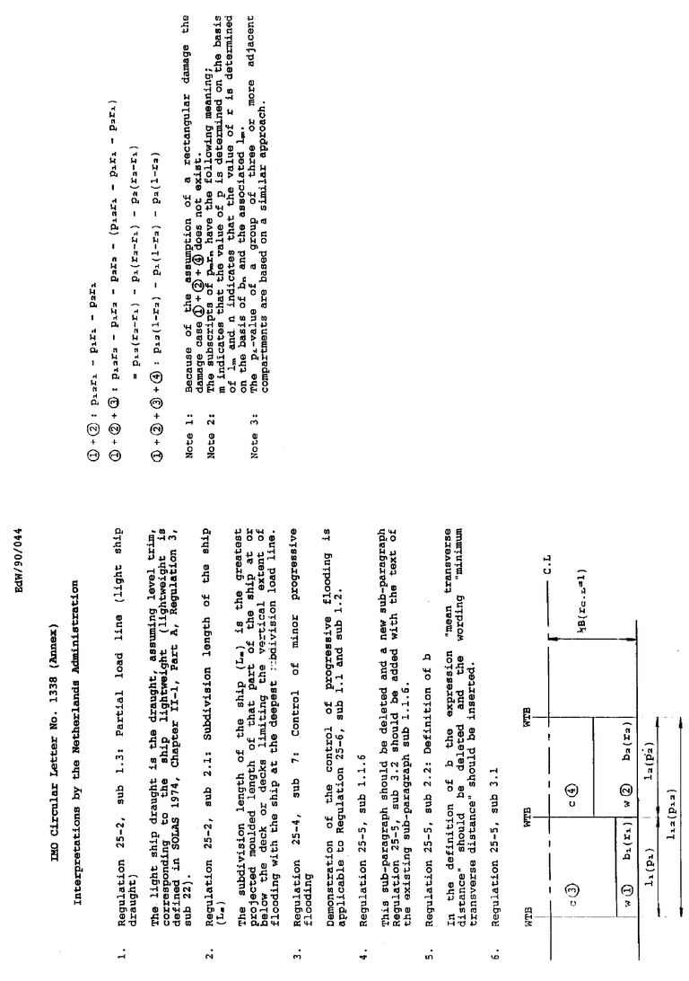
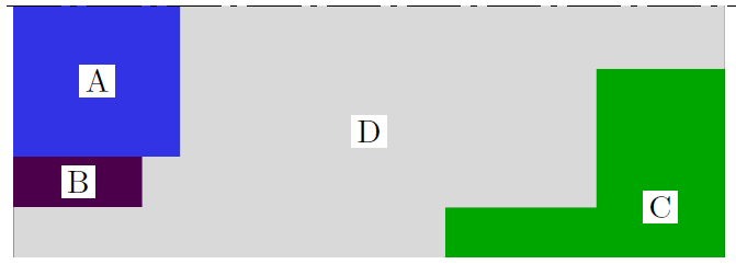
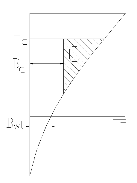
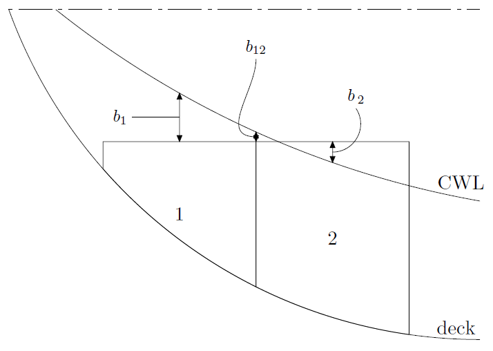
The penetration depth b is the penetration (in meters) up to the inner damage boundary. However, if this distance is measured from the waterline, and the inner boundary is located beyond the local waterline breadth, a logical inconsistency pops up, see the cross section figure below. With damage to compartment C only, the matter is that Bc > Bwl, so the penetration = Bwl - Bc < 0, and consequently the probability of damage p will be zero. And that is the problem, because we have a real damage case at hand, with a real penetration through real steel, which is not included arithmetically as a damage case in the context of probabilistic damage stability. For this reason this option offers the choice between two alternatives:
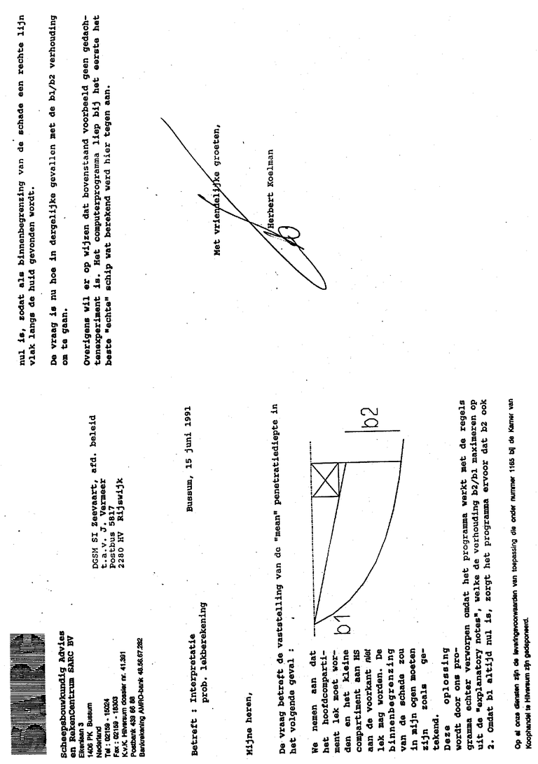
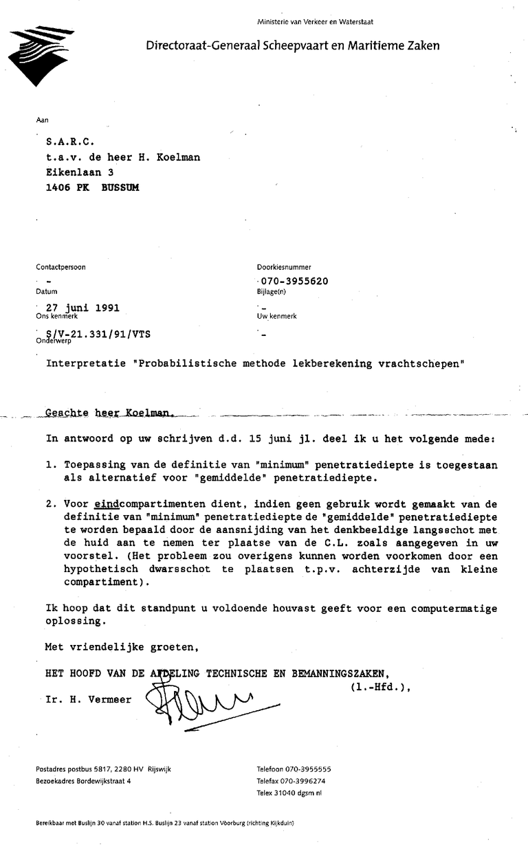
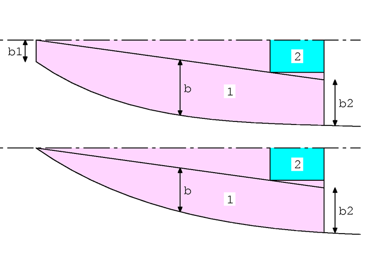
According to the explanatory notes of SOLAS 1992 the penetration at side compartments is limited by the rule that the maximum penetration shall not exceed twice the minimum penetration. This constraint can limit the penetration depth very severely, see e.g.the figure below, where only compartment 1 is damaged. The evident penetration is according to the angled line, with the penetration depth indicated by b. However, in this case the minimum penetration, b1, is zero, so the maximum penetration b2 is always greater than twice the minimum penetration, violating the penetration constraint rule. The only solution to comply with this rule is to set b2 also to zero, which results in (an unrealistic small) penetration depth b as depicted in the second figure. With a hollow waterline b would even become negative, which leads to a probability of damage of zero for this rather realistic damage case.
At this option ‘Application penetration constraint (b1,b2)’ it can be specified whether, and how, this rule is applied. The options are:
As mentioned, the penetration constraint rule of SOLAS 1992 reads that the maximum penetration may not be larger than twice the minimum. For SOLAS 2009 & 2020 the rule is slightly different, it reads that the mean penetration may not be larger than twice the minimum. Therefore the program offers a choice of two alternatives, where the SOLAS 1992 version is formulated as ‘b1,b2 < 2.min(b1,b2)’, and the 2009 & 2020 one ‘bmean < 2.min(b1,b2)’.
Here it can be specified (onl;y with the zonal method) what the program should do when the (b1,b2) penetration constraint is exceeded:
This choice is related to the determination of penetration breadth b (see e.g. SOLAS 1992 reg. 25-5.2.2). Three choices are possible here:
The choice between the three alternatives is left to the user, we can only mention to have observed that the minimum interpretation requires the least computation time.
This option determines the way how with a multi-compartment damage with longitudinal subdivision the reduction factor r is determined. The first possibility is local dimensionless penetration b/B, where the r of each to-be-subtracted damage case is determined with the individual b/B as measured halfway the waterline of that case. The other choice has the effect that the r of each damage case (so the main damage as well as the damages to be subtracted) is determined on basis of a common dimensionless penetration b/B. The exact implementation depends on the selected calculation method:
In 1992 SOLAS and IMO A.265 the penetration of side damage was limited to centerline. In SOLAS 2009 the penetration is B/2, without further addition. That implies that with SOLAS 2009 in the regions of the narrowing waterline, in foreship and aftship, the damage will extend beyond centerline. With this option one can choose between these two variants. This option is, for now, not available for the ‘numerical integration’ method. It is not because this would be infeasible, on the contrary, but the combination has never been required.
Here is can be specified how to process a combined longitudinal and transverse subdivision. If r is taken outside brackets than the equation for a three-compartment damage reads pr = r123.(p123 - p12 - p23 + p2), if r is not taken outside brackets pr = r123.p123 - r12.p12 - r23.p23 + r2.p2 is used.
As illustrated by the text and the figure just above, the formulae structure as laid down in the legislation can give rise to the occurrence of negative probabilities of damage. Some people accept this as the mere outcome of the SOLAS system, while others get restless at this, because it is obviously mathematical nonsense. For the latter this setting is available; if one enters ‘yes’ here, then the probability of damage is maximised to zero (i.e. if the probability is less than 0 then 0 is taken). With ‘no’, for the collision probability the SOLAS formulas are simply followed, without special treatment of negative probabilities.
Please see that the choice ‘yes’ is not supported by SOLAS. This provision is, among other reasons, included in PIAS because reportedly other computer programs exist where default (and invisible) negative probabilities are raised to zero, so that they are hidden away. With this setting, PIAS can do the same.
With ‘no’ the damage stability calculations are only performed for the final stage of flooding, with ‘yes’ also the intermediate stages 25%, 50% and 75% are computed.
Besides for the computation of probabilities of damage, the numerical integration method can rather well be used for the generation of damage, so a distinct generation step can be considered a bit redundant. With ‘yes’ at this option it is specified that the generation of damage cases and the execution of the calculation must be combined, with ‘no’ they are separated.
So that no damages will be generated larger than this value. At SARC, in general we see little reason to deviate from the default value of hald the ship length.
With Z given here, no damage cases will be generated with more than Z simultaneously damaged compartments (or subcompartments, in case of the subcompartment method). This parameter should be chosen with care; a too small value will result in a limited number of damage cases, and hence a low attained subdivision index. A high number will produce the maximum A, but that may require a high number of damage cases with a corresponding long computation time. A scrisp number cannot be recommended, that depends on the nature of the subdivision and on the number of compartments. At SARC we tend to start at ten, and may adapt this parameter dependant from the computation result.
By the way, the absolute maximum number of damage cases for this module is 5000, that has nothing to do with this parameter.
When using the zonal method the program will generate all combinations of adjacent zones. This could lead to large amounts of damages, from which the majority of multi-compartment damages could preponderantly not contribute to A. In order to limit the number of damage cases, with this option the maximum number of zones per damage can be specified.
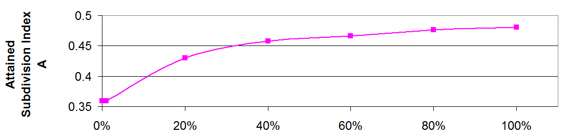
With the numerical integration method the integration step size plays a role; it may be clear that the accuracy increases with a decreasing step size. The real step size is determined by means of an algorithm, on the basis of the number of compartments etc., and it is not considered relevant to confront the user with it. For that reason the accuracy is defined by means of an index, where 0 indicates the least accuracy and 100 the greatest. One might be inclined towards the greatest possible accuracy, but that of course also induces a longer processing time. The exactly required accuracy cannot be indicated in general. Apart from your patience it does also depend on the vessel's layout. In order to give an impression one can imagine two extremes, one extreme is a barge with completely rectangular subdivision. Because the program applies an integration step at each (sub-)compartment boundary, all spaces are already taken into account completely, so the result will (approximately) be independent from the accuracy index. On the other hand, in case of a vessel with angled bulkheads the number of integration steps does play a role, for illustration purposes we have created a barge with only a single longitudinal bulkhead, which is extremely twisted. The required subdivision index A as a function of the accuracy index is plotted in the figure. It will be obvious that in reality the quantitative effect of this index will be somewhere between these extremes.
With ‘yes’ the damage cases will be generated including horizontal subdivisions (decks) between the compartments. With ‘no’ the horizontal subdivisions will be ignored, so the damages will extend from baseline to the uppermost deck, leading to less damage cases.
If compartment connections have been defined (see Define compartment connections for more details), then with this option it can be specified that at the generation of damage cases the program will model the flooding of compartments through pipes by means of complex intermediate stages of flooding. This option is only relevant for the (pre 2021) method of complex stages, please refer for that method to Complex stages of flooding (before 2023).
For verification purposes the contributions of all numerical integration steps are also included in the text file with intermediate results (When PIAS' multithreading function is active, multiple integration cycles are executed concurrently. A side effect is that these intermediate results are not included in the textfile in a synchronized fashion. If synchronicity is required, multithreading should be switched off, which can be done with the external variable no_multithreading, as discussed in Fairway). With a large accuracy index the number of integration steps can be quite large, and the text file might consequently rise to enormous proportions. To avoid that, it can be specified at this option to exclude the integration steps from the text file.
The text file, as discussed in the previous option, is intended for human interpretation. For an analysis of the computational results it might be handy to have the figures available in a spreadsheet. If that is specified at this option, the results will be written in a .CSV (Comma Separated Values) file, such a file can be read with most spreadsheet programs. However, such a spreadsheet file can only be generated if the configuration options listed below (Re-use unmodified results of former calculations) is set ‘off’. The reason is that all results actually must have been calculated before they can be included in the spreadsheet file.
In order to increase the computation speed this module keeps quite some results of former calculations in memory. These can be re-used in subsequent calculations. For example, for each damage case the KNsin(φ) are stored, so that in case of future modifications of VCG' the GZ in damaged condition can be rapidly determined. In general it is recommended to use this facility, but if it is not desired for whatever reason it can be switched off at this option.
Damage cases can be plotted. With the option under consideration it can be specified if these plots are requested in portrait or in landscape format.
Here the data for the various components of the heeling moment can be given, which are required for the calculation of passenger vessels.
In Calculation method, configurations and ship parameters the subdivision draft and light draft have already been specified, with which the calculation drafts are fixed. In the present menu for each of those calculation drafts the following particulars can be entered:
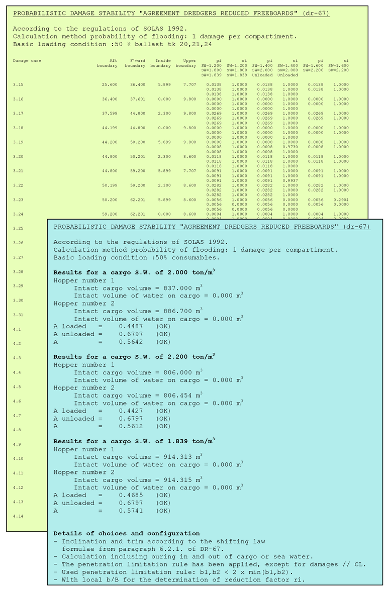
This module is also capable to calculate the probabilistic damage stability according to the regulations ‘Agreement for the construction and operation of dredgers assigned reduced freeboards’, a.k.a. dr-68. See for all details of hopper stability Probabilistic damage stablity.
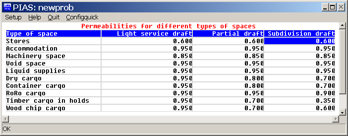
According to SOLAS 2009 & 2020 the several kinds of space types must be computed with different permeabilities (μ). The μ's which belong to each type of space can be inspected with this menu option. With module Layout the correct space type will have to be assigned to each compartment, where one should verify that all subcompartments of such a compartment have their ‘Autopermeability’ set to ‘yes’, otherwise the static μ will still be used.
The permeability list of View scheme of standard permeabilities covers those types of spaces which are explicitly defined in SOLAS 2009 & 2020. Possible additional categories can be defined with this option.
This function co-operates with PIAS' system for complex intermediate stages, the development of which was frozen in 2021 because a more capable system called Consecutive flooding was released by then. When using that, this specific Probdam function is no longer needed, so it will be inactive then. For more information, see Background from tools for ship-internal connections in PIAS.
In this menu for each compartment can be specified which compartments are flooded in the case of damage to the compartment under consideration. In particular one should consider the flooding via damaged pipes. This menu consists of a matrix of connections, between all compartments, where in the first column all compartments are linked to a number that corresponds to the numbers in the header line. With these numbers it is clear which two compartments are connected. The connection between the two compartments can also be found textually in the status bar.
In almost every cell, two connections can be specified for two compartments by using the ‘Connections popup’. All settings in the popup are explained in more detail below, using the compartment connections menu. In addition to the popup, an ‘Open’, ‘Pipe’ or ‘A-bulkhead’ connection can be made between the two compartments using the <O>, <P> and <A> keys respectively.
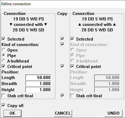
Double-clicking on a compartment name — in the second column — opens a menu where all connections to and from the selected compartment can be defined. For each connection it must be specified whether it exists by means of ‘Selected’. If such a connection exists, the type of connection must be defined, which can be one of the following types:
Additionally, it can be specified whether the connection always exists, or only after the water level at a certain point is exceeded. The latter can e.g. occur with a bulkhead which does not extend over the full height. In this case the column ‘Cr.pnt’ — an abbreviation of Critical Point — should be marked ‘yes’, while at Lcrit, Bcrit and Hcrit the longitudinal, transverse and vertical coordinates of that point must be specified. In addition to the ‘Critical Point’, one can also specify whether the connection should be checked against the criteria for the intermediate or final stage of flooding. Normally this setting is No, but in some situations it may be desirable or mandatory to test against the criteria for the final stage. Please note that, if the regulations have not specified criteria for intermediate stages - eg for cargo vessels under SOLAS 2009 - the criteria for the final stage will be used.
In this menu there is also a ‘Copy’ column with which the entire connection between the compartments to be connected can be copied. Normally the following applies to a connection; if one compartment, say compartment A, is connected with another compartment, say compartment B, it does not imply that B is automatically connected with A. In reality that does also not necessarily has to be the case, e.g. when a pipe is fitted in compartment A which will flood B if damaged. That mechanism does not apply reversely, so at damage of compartment A, B will also be flooded, but at damage of compartment B, A remains unaffected. If there exists a permanent opening between A and B, one should explicitly specify that A is flooded in case of damage to B. This explicit task can be taken care of by setting the copy to ‘Yes’. It is worth noting that in the connection popup, from the matrix menu, copying can be done in a more selective way.
The values specified here are solely used at the generation of the damage cases, in other words, these data are not used independently, but are processed in each individual damage case. So modified data will only be processed after re-generation of damage cases.
Two more remarks can be made on this option:
| Stage | A | B | C |
| 1 | 100 | 0 | 0 |
| 2 | 100 | 100 | 0 |
| Final | 100 | 100 | 100 |
The compartments defined in PIAS are the real enclosed spaces of the ship. However, in a vessel on a less detailed level often ‘primary spaces’ or ‘zones’ can be identified, where multiple compartments can be situated in such a zone. An example of a zone is the engine room, regardless the exact layout of the many consumable compartments. So a zone boundary is an abstract notion, it does not always have to coincide with a physical bulkhead. Zonal boundaries can be specified for two purposes:
Please note that the longitudinal zone boundaries are specified as absolute values for the side of the vessel for which the calculation is executed.
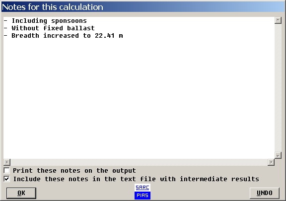
With this option a window appears where free notes about the calculation or the configuration can be written. These notes are saved with the calculation. It can also be specified whether these notes must be printed on the output, or in the text file with intermediate results.
With this option all existing damage cases will be deleted and all possible (up to a maximum of 5000) damage cases will be generated. This might, notably with a large number of damage cases, take quite some time, which significantly be reduced with the use of multithreading see Speed enhancing mechanisms in PIAS: PIAS/ES
The name by which each generated damage case is identified depends on the setting of ‘Identification of the compartment in the tank sketches’ as discussed at Settings for compartments and tank sounding tables :
With the (sub-)compartment method the progress will be shown in the Multithreading task monitor. Damage cases are generated from the forward- to the aft side of the vessel and per thread it is shown from which forward boundary damages are generated.
With the (sub-)compartment method the damage cases as generated with this option are only based on the (sub-)compartment geometry. So the initial damage cases are determined by the extreme compartment boundaries. During the computation of the damage stability calculation the true damage boundaries will be determined, taking into account all boundary conditions. For this reason it might occur that a generated damage case after all is not able to exist, within all statutory limitations. Especially the penetration constraint rule b1/b2 plays a role to this effect. If a damage case does not exist, the warning ‘Damage impossible’ is included in the .PD0 file with intermediate results, please also refer to Warnings.
With the previous option all existing damage cases will be removed and new damage cases are generated. The present option also generates damages cases, but these will be added to the existing damage cases. Four selection criteria must be specified here:
With this option complex intermediate stages of flooding were generated, where compartments below a certain, user-specified,height get a zero percentage of flooding. This option could be used to simulate minor damages. After December 2021 the high sub damages are generated and calculated automatically, if the setting at the input of damage cases is selected.
With this option, which sorts and collects damage cases, is only relevant for the (sub-)compartment method, it is not related to the zonal method as distinct calculation method for the probability of damage. This sorting is based on the zonal boundaries as specified in Define zonal boundaries. After sorting, those damage cases which fall into the same zone are collected, while subtotals for all zones and combinations of zones are printed. One must recognize the fact that the calculation process of PIAS does not change when using zones, it only affects the presentation of the output. While sorting, the damage cases can be renamed if you have chosen to do so. In that case the name of a damage case is composed in the form of K.L.M.N, where:
With the (sub-)compartment method the user has to specify all damage cases (where a damage case is a collection of one or more damaged compartments) which can occur within the vessel. That can be done with the present option, which is discussed in general at Input and edit damage cases. In addition, here at the probabilistic damage stability a number of additional columns are present in the text window:
If a new calculation is performed, the former exact determined values can sometimes change a bit. The listed values are used as the initial values for the new calculation of damage boundaries, and if the initial values for two calculations differ to some extent, the final boundaries may also slightly differ, please also refer to Computing the damage boundaries.
Because the probability of survival is composed of the sum of the probabilities for all damage cases, all cases normally have to be included, so all ‘Slct’ values should be set to ‘yes’. In certain (investigation-)cases it could be handy to leave cases temporarily out of the calculation, in which case those cases can be set to ‘no’.
If the text cursor is placed over a damage case and <Enter> is pressed, a window appears where can be specified which compartments (as defined in Layout) are simultaneously flooded in the damage case under consideration. this is also described at Input and edit damage cases. In the context of the probabilistic damage stability an additional column is present, ‘valid for pi, vi and ri’, which is normally to be set at ‘yes’, which means the flooded compartment is taken into account for the determination of the probability of damage, pi, vi en ri. If this column is set to ‘no’, this compartment is not included in the probability of damage, however, it will obviously still be included as a flooded compartment. This might be the case when a compartment is not located in the damaged region but yet flooded anyway, for instance if it is connected to a damaged compartment by means of a pipe.
As mentioned, in the module Re-use unmodified results of former calculations a mechanism is incorporated with which the results of unmodified formerly calculated damage cases are maintained. With this mechanism the processing time at repeating calculations with slight variations can strongly be reduced, because only those damage cases which have actually been modified need to be re-calculated fully. This module automatically keeps books of compartments, damage cases and intact particulars. A prerequisite for a correct bookkeeping is that the computer clock functions well. With the present option the user can remove all these accumulated results.
With this option all complex intermediate stages of flooding will be removed (see Complex stages of flooding (before 2023) for the ‘complex stages’ mechanism).
Damage cases with a negative probability of damage will decrease the attained subdivision index A. With this option they can be removed. Please realize that as a consequence of this action the whole damage case constellation will change, and, with the (sub-)compartment method, consequently the whole damage case subtraction scheme, which might on its turn cause other damage cases to get negative probabilities.
Damage cases with a non-positive ai are removed. It is better not to use this option when in a later stage the VCG' could be decreased. Damage cases with zero probability of survival will be deleted with this option, and it might very well be that with a lower VCG' some of those damage cases would have a positive survival probability.
With this option all existing damage cases are simply removed.
With this option the computation is executed, and printed. This might, notably with a large number of damage cases, take quite some time, which significantly be reduced with the use of multithreading, see Speed enhancing mechanisms in PIAS: PIAS/ES.
The progress will be shown in the Multithreading task monitor. Each thread shows the damage case it is calculating with the start-, and elapsed time and the status of the thread.
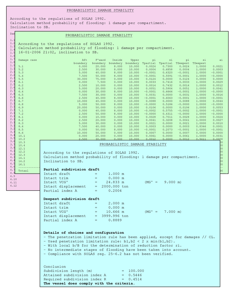
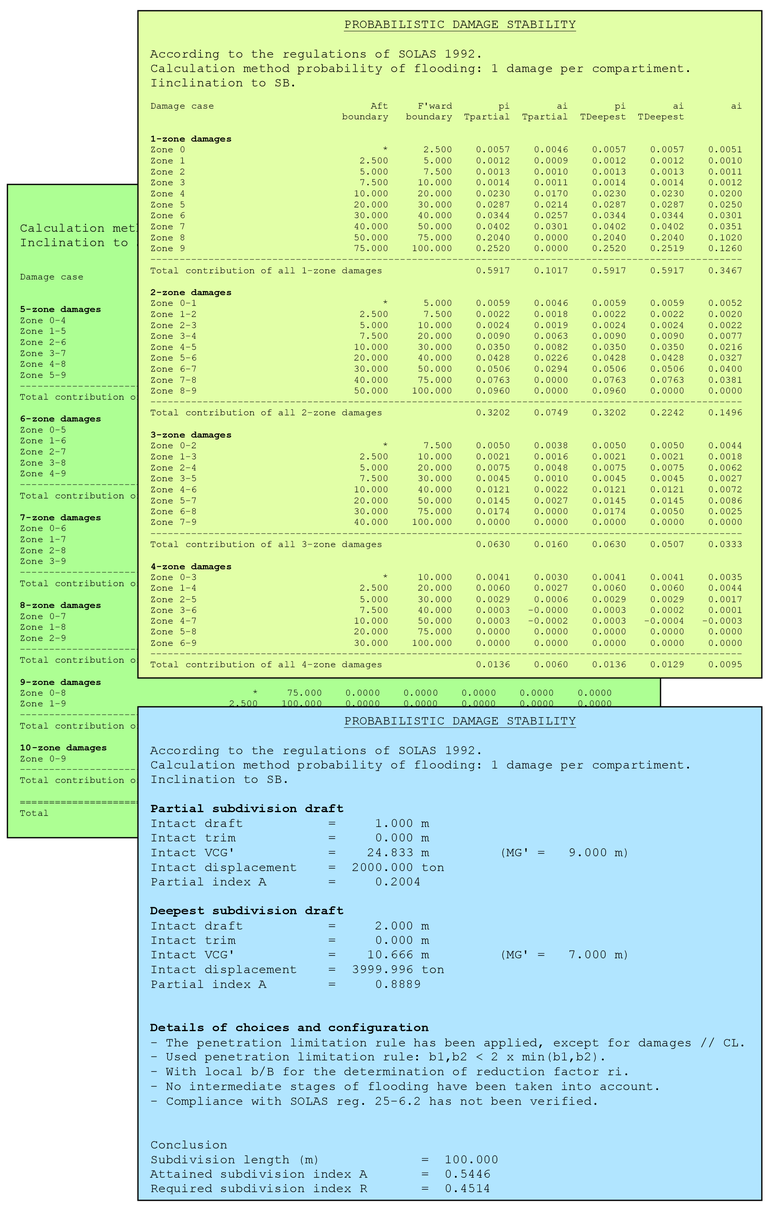
An example of the output of a dry cargo vessel is given in Appendix 4: output of an probabilistisc damage stability calculation for a dry cargo vessel, and that of an open hopper vessel (according to regulation dr-68) in Appendix 5: output of an probabilistisc damage stability calculation for a hopper dredger.
In this output pi is the probability of damage, so including the effect of reduction factor r (which accounts for transverse penetration) as well as reduction factor v (which accounts for horizontal watertight subdivision above the waterline). Probability of survival si, as included in the output, is what the name implies; the pure survival probability, based on properties of the residual GZ-curve. This is a slightly different grouping than applied in the regulations — where p×r is baptized “probability of flooding” and s×v “probability of survival” — however, that is a bit of an awkward formulation because it stirrs up the two types of probability. Fortunately, for the final results this grouping issue is irrelevant, because the contribution ai to the Attaineed Subdivision Index A will be p×r×v×s in all cases.
As mentioned earlier, in order to enhance execution speed as much as possible, the program keeps track of results of former calculations. Under the condition that the underlying ship data are not changed, these results can be re-used, entirely or partially, at subsequent computations. This mechanism can be the reason that where an initial calculation can take hours to complete, repetitive and identical calculations can be finished within minutes.
Furthermore, please observe that at the end of the table with damage cases, on the output, the sum of all probabilities of damage p is listed. This sum, Σp, represents the ‘total probability of damage when damaged’ and gives an indication whether the selected damage cases are correct and complete. There are three possibilities:
Unfortunately, the practice is often stronger than the doctrine, will Σp often not become exactly 1, also with a correct set of damage cases. So, in practice we are already satisfied if it is in the neighbourhood, e.g. between 0.9 and 1.13 — or 1.15, or 1.17, this limit is not strict.... This phenomenon applies in particular to the (sub-)compartment method, and is discussed in [2], [3] en [8].
Finally, it must be mentioned that besides probabilistic criteria the regulations could also contain deterministic damage stability criteria,. The computation of deterministic damage stability is not a task of this module, that can be performed with another (dedicated) PIAS module Loading. For instance reg. 25-6.2 of SOLAS 1992 requires essentially that every fore peak damage must be survived with s=1 (that is, GZMAX ≥0.10 m, range ≥20° and θstatical ≤25°). That this rule is not verified is reported by the program by the message “Compliance with SOLAS reg. 25-6.2 has not been verified”.
These options will speak for themselves. With the first computations are only executed, nothing is printed. With the second the available results of the last computation are printed (again).
Complete calculation results can, because of their extent, be rather indigestible. It could be convenient to structure the results within zones. If with Define zonal boundaries zonal boundaries have been defined, then with the present option the output can be arranged and printed in zones, see Appendix 6: collecting the output in zones for an example. This restructuring within zones can be applied with the zonal method and the (sub-)compartment method. In principle the numerical integration method does not use the ‘damage boundary’ concept, and consequently it cannot be determined in which zone a damage case is located.
At the execution of the computations many intermediate results are generated. In order to provide the possibility to analyse or verify a certain computation, these intermediate results are saved. With this the intermediate results are shown. Only the intermediate data of the last calculation will be available via this option (the file will be re-written when a new calculation is performed). If the user desires, these intermediate results can be saved for future reference. Please note that if the option Re-use unmodified results of former calculations is used, this will be mentioned in the intermediate calculation data as statement instead of the full data for the corresponding damage case(s). When you require intermediate calculation data with all information, this option should not be used or be removed explicitly, see Remove all results of former calculations.
Except from the subdivision, the attained subdivision index A is also dependant on the vertical center of gravity VCG'. In general the index will rise with decreasing VCG', so there will be a single VCG' for which A is exactly R. With this option this critical VCG' is determined. One aspect is that multiple drafts with belonging VCG's are in play, and that no general rule can be postulated for the distribution of the VCG' variation over the drafts. Therefore, at Drafts, trims and VCG's the user has to assign the single draft for which the critical VCG' is determined.
Backups of the Probdam data can be made and restored here. Here is also the option ‘Quit module without saving the data’. See for the details Data storage and backups.
There is a direct relationship between compartment boundaries and damage boundaries, however, when applying the zone method the user will have to define the zonal boundaries manually, so no use will be made of the already available compartment geometry. When the compartment method (as weel as with the subcompartment method, see Calculation method probability of flooding for those methods), the relationship is evaluated, so that the damage boundaries can be automatically determined. For this prupose, a search algorithm is used that ‘plays’ with the damage boundaries so that:
Incidentally, multiple damage bondaries may exist, which all lead to the flooding of the intended compartments, and all have more or less the same size. One of those is chosen, by “coincidence”. It can even occur that at one time a slightly different combination of damage boundaries is found than at another time, which might be caused by one of these reasons:
This is not disturbing, both solutions can (and will) both be correct. Moreover, by application of this genetic algorithm it might occasionally occur that damage boundaries are sometimes found and sometimes not. Could that be made more consistent? Yes, but only against a serious increase in calculation times, which is a (too) high price to pay for this occasional effect in damage cases with a marginal effect.
During the calculation Windows might occassionaly report that the program is not responsive anymore. This message is incorrect and can be ignored, for its background please see Frequently asked questions. Sensible warnings may be included in the text file with intermediate results (.PD0 file), and have the following meanings: