Import PIAS compartments from pre-2012 format
With this option compartments are imported in the format of the precursor of Layout, Compart (which has been in active use until 2012 for modeling compartments), and converted to Layout compartments of the type ‘with coordinates’. The user is supposed to choose the old file, its extension is .cmp.
Clean pre-2012 PIAS compartments
In the old PIAS compartment module Compart subcompartments could only be limited by eight vertices. Apart from that, there was the requirement that they should be convex, and in the test on convexity vertices were not allowed to converse precisely. That resulted in defining vertices for, for example, three-sides or tapered compartments with differences of millimeters. Here, in Layout, this is no longer necessary, and being more serious, those differences of millimeters are counterproductive, because when Layout is constructing physical planes, then there is actually made a plane of one millimeter, and that does not make for overview. The present option detects those differences and almost converging vertices are actually contracted. One must realise, however, that this option does not repair all anomalies, so that manual adjustments might be necessary, for example in the event of:
- Larger differences than two millimeters. The algorithm would be capable of that of course, but it remains to be seen to what extent a program must change the data imported by the user autonomously.
- A boundary of a subcompartment that is warped (so, not fully flat). Within a subcompartment of the type ‘with coordinates’ there is no objection against this property, however, this cannot be used to generate physical planes (for they have to be entirely flat).
Generating physical planes (a feature that has passed its expiry date)
These options are intended for generating physical plane, based on the existing compartments of the ‘with coordinates’ type. However, there are a few comments to be made:
- There will be countless combinations of planes that yield exactly these compartments, and which are therefore all correct as such. However, it would be quite a coincidence if the solution found were the one that best follows the logic of the basic ship subdivision.
- This conversion was made for compartments of PIAS' compartment module from before 2012, which did not have the physical planes facilities at all. As a service during the transition at the time.
- It is much more convenient to start each ship design directly with physical planes, because a) that is what they are intended for and b) then nothing needs to be converted at all.
In short, take advantage of this facility, but use it in moderation. Deze generation feature has two sub options:
Generate physical planes from the totality of convertible subcompartments
This option does four things. First, an overlapping check is carried out, which is entirely identical to the second option in this menu (see Apply advices on converting to physical planes), where subcompartments of the type ‘generated between planes’ can be converted to the type ‘with coordinates’. At this test is also checked whether subcompartments overlap, and if so, the convertibility of one of the two, namely the smallest one, is switched off, so it is omitted at the conversion. Subsequently, all physical planes are removed, after which a new collection of physical planes is generated on the basis of the subcompartments of the type ‘with coordinates’ that mutually constitue exactly those subcompartments. Finally, all those subcompartments are converted to the type ‘generated between planes’. It is not compulsory to use all available compartments at this action; through the setting ‘convertible’, which can be defined in the compartment list (see Compartment list, calculation and printing of tank tables), at the compartment definition (see Convertible) and the subcompartment definition (see Convertible) one can exactly indicate which (sub)compartments are included in this conversion and which ones are not included.
- Attention
- It is advised to use this conversion option tactfully. It may be tempting to convert a complete ship, with all its compartments and tanks, to the combination of physical planes and the subcompartment type ‘space generated between planes’, which is possible and allowed, but one may end up with a large amount of physical planes, without any overview, as a result of which it is useless in the end. It is probably wiser to confine oneself at the conversion to compartments that belong to the main division of the ship, and is also stimulated to do so because the maximum number of convertible subcompartments is 150 (which is not a principal limit, but a practical one). Please also consult what has been written at Use of different types of subcompartments.
Apply advices on converting to physical planes
This option is meant to support the generation of physical planes from subcompartments of the type ‘with coordinates’ (see Generate physical planes from the totality of convertible subcompartments), since that is only possible with non-overlapping subcompartments. First of all is considered here whether there already are subcompartments of the type ‘space generated between planes’, and if so, then the user is asked whether these have to be converted to the type ‘with coordinates’, because the generation of physical planes is only possible on the basis of this type of subcompartments. Subsequently is tested which subcompartments overlap. A report is given of this (when this is very long, it can be cut and pasted to word processor for further printing or further study). At all compartments of which has been defined that their convertibility is ‘automatic at conversion’, is filled in at the smallest subcompartment of the two overlapping ones that this may not be included in the conversion.
Export decks and bulkheads to Rapid Prototyping format (STL)
With this option bulkheads and decks are converted to STL format, which is suitable for Rapid prototyping (or 3D printing). This option is still experimental, and only available to SARC. On www.sarc.nl/images/publications/appendix_swz2012.pdf is an example of how to use such STL file in order to print a ship's subdivision three-dimensionally.
Export to Poseidon (DNV•GL)
With this option data from PIAS are converted to and written to a file in the format of Poseidon, the rules program of DNV•GL. The purpose of this conversion is to transfer the data as available in PIAS to some degree of completeness. The created Poseidon file contains the following data:
- Main dimensions and other general numerical data. For this purpose, please do not forget to define the ‘auxiliary particulars’ as well, see Particulars of export to Poseidon. The minimum drafts aft and fore, which must be communicated to Poseidon, are derived from the draft marks. So, for a Poeidon file as complete as possible, at least two draft marks with a so-called ‘Tmax local’ must be given, see Draft marks and allowable maximum and minimum drafts for further guidance. Poseidon parameters for which no data are available in PIAS (such as GL register number and ice class particulars) are left void.
- Table of frame spacings.
- The hull form, represented by all frames of the PIAS model.
- The shape of longitudinal bulkheads and decks.
- The shape of transverse bulkheads, modelled as ‘transverse web plate’ for Poseidon.
- Compartments.
- Global loads: the (envelop of) longitudinal shear forces and bending moments.
- Local loads: deck loads, compartment fillings and wheel loads.
- Girders and webs.
- Plating of shell, bulkheads and decks, with a default plate thickness.
- Longitudinal and transverse stiffeners on shell, bulkheads and decks.
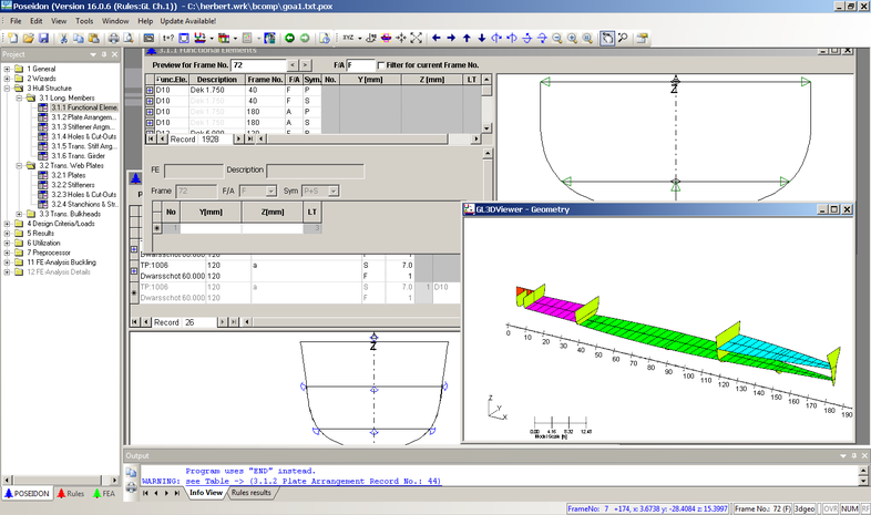
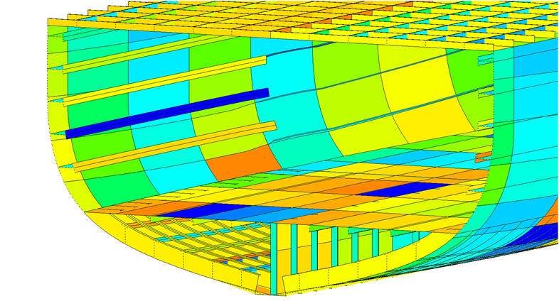
Ship with bulkheads and decks exported from PIAS, imported and vizualized in Poseidon.
Enter additional Poseidon data in Layout
Many details of geometry of hull and layout are already available in Layout, so these can be converted to Poseidon without additional effort. However, Poseidon also requires data that is not at all available in PIAS, such as local loads or structural data. Layout offers some alphanumeric input menus to enter those data. For that reason with this “Poseidon” export feature, an intermediate menu will open, from which the first option invokes the actual export to Poseidon. The other options open forms in which specific Poseidon parameters, which are not available in PIAS, can be specified. Some of these parameters are all of Poseidon, so for their meaning and application reference is made to the Poseidon manual. On data of a more generic nature the following elucidation is applicable:
- For the purpose of Poseidons “Cargo and Decks” in one of the tables deck loads can be given. In the first instance you must specify a deck, for which one of the physical planes of Layout should be identified means of its abbreviation (one can actually give any kind of plane, including a transverse or longitudinal bulkhead, but that would be quite useless for deck cargo). The heart of the matter is that the deck cargo will be placed on that particular deck. Additionally, a compartment / subcompartment combination is given, which is used exclusively for the position and length of the cargo (the verification whether the deck is indeed adjacent to the subcompartment is up to the program user). An exception to this mechanism is a load on the upper deck. To this end one gives the Poseidon term “Tdeck” as ‘abbreviation’, as well as a compartment / subcompartment combination which is adjacent to the top of the hull. The fact that this subcompartment is located under deck instead of above does not matter, it is just used to indentify the location.
- In addition to deck loads, for “Cargo and Decks” also tank fillings can be specified . These are automatically applied to the physical plane which is located at the bottom of a compartment. A combination of tank filling and deck cargo on the same deck is obviously not feasible. Would that be specified anyway, the the deck cargo prevails above the tank filling.
- Webs (transverse girders) can be given per group, with for each group an aft boundary, forward boundary and spacing between two webs. For each web group a start and an end must be given. The orientation (from inside out, or from bottom up) is not constrained. Start and end are situated on the shell, or on a Layout plane, which can be either a reference plane or a physical plane. These planes are specified by the user by its abbreviation, or, alternatively, the Poseidon concepts “Tdeck” or “Shell” for deck or bottom/shell respectively. For start and end points are further given:
- The Layout plane on which (in which) it lies, or, alternatively, shell/bottom/deck, is the web is attached to that. This will be called plane 1.
- The position of this point in plane 1. Basically, a transverse or vertical coordinate, however, in order to maintain the coherence with the other components of teh ship layout, reference is made to another plane instead (or, alternatively shell/bottom/deck) — which will be baptized plane 2 — so that start/end point will be situated at the intersection of plane 1 and plane 2.
- The inner limit of the web, which will fix the girder height at that location. For this point a third plane (plane 3) must be given, which defines the inner limit at the intersection of planes 2 and 3. Additionally, an optional offset from plane 3 can be given. Alternatively, for the web a constant girder height is specified, in which case plane 3 is omitted. If start and end points share the samen ‘plane 1’, and if that is a physical plane in Layout, then with a constant girder height the inside will run parallel with the outside. In this way a web along the shell can be defined.
With these parameters quite some variations in structural layout can be defined, as illustrated in Examples of defining girders and webs. With a web two Poseidon-related details are relevant:
- It is not crystal clear how Poseidon determines at which side the girder height should be taken. In one instance it is at the left of ‘plane 1’, in another at the right. So it will require some experimentation to discover the rule behind.
- From a web it can be specified whether it is situated at PS, at SB or at both sides. In Poseidon this is interpreted loosely, which means that a web shape is simply copied to the other side, even if the plane to which the web refers does not exist at that side.
- Girders (longitudinal) are defined similar to webs, just the wording can differ now and then. A group of girders is given in transverse or in vertical direction, so angled directions are excluded. Transverse coordinates whould be given only positively; the switch PS/SB/Double determines the applicable side (this is, after all, the way Poseidon works).
- Specifying webs and girders in PIAS is aimed at a quick — and integrated in the Layout structure of bulkheads and decks — definition of the primary structural elements and the most commonly used web/girder configurations. However, not each and every variant is supported by this PIAS mechanism.
- Stiffeners on web plates are easily defined by giving the abbreviation of a Layout plane or Poseidon element “Tdeck” or “Shell”. Now define the start and end point of the stiffeners moulded line and the centre to centre distance and number of stiffeners. Now the only things left are, on which side the stiffener should be positioned and defining the type and dimensions of the stiffener and how it's positioned in regard to it's moulded line.
- Transverse and longitudinal stiffeners on longitudinal plates are defined in a similar way as stiffeners on web plates. There two additions namely:
- For transverse and longitudinal stiffeners on longitudinal plates one has to define a longitudinal start and end so instead of defining one begin and end point for the stiffeners moulded line there are now two, one on the longitudinal start and one on the longitudinal end. The begin and end point of the stiffeners moulded line will be interpolated in relation to the element on which the stiffener is located, decks and longitudinal bulkheads have a fixed interpolation direction but the Poseidon elements “Tdeck” and “Shell” can be set to vertical or transverse.
- For the longitudinal stiffeners on longitudinal plates there is the extra option to define the rotation of the stiffener in relation to the moulded line of the stiffener. One can also define a rotation which is relative to the element on which the stiffener is positioned.
- Defining the plate fields is achieved by giving the abbreviation of the Layout plane or Poseidon element “Tdeck” or “Shell” and then defining a standard plate's dimensions as well as the moulded line of the Layout plane or Poseidon element. The physical area of the Layout plane or Poseidon element will be split into a bunch of plate fields with the afore mentioned standard plate dimensions. This division is handled in a specific way for each element:
- Longitudinally, from the aft to the front; Transversally, from the centreline to the outside; Vertically, from the bottom to the highest point.
- The specific Poseidon elements “Tdeck” and “Shell” are handled in the same way as Layout planes but the specific geometric definition of these elements is outside PIAS's control.
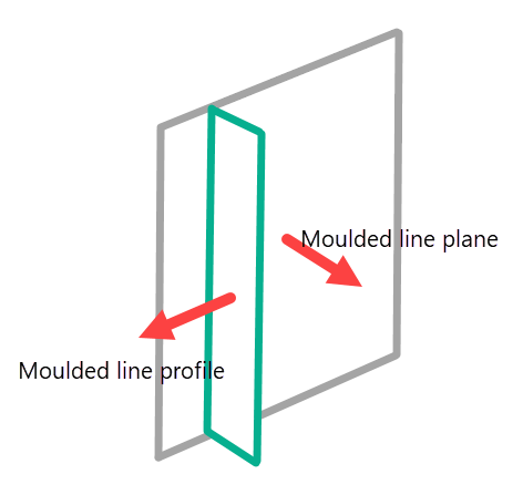
Definition moulded line plane and stiffener.
Examples of defining girders and webs
Example 1: There are always two intrinsic planes present namely ‘Shell/deck’ and ‘maindeck’. And lets make, for convenience, ‘centreline’ (CL) also intrinsic. The web with fixed height H, as seen in the picture below, is defined by:
- Begin point plane ‘Shell/deck’ on intersection with CL.
- End point also plane ‘Shell/deck’ (this is neccessary because we are using a fixed girder height) on intersection with ‘maindeck’.
- Fixed girder height H.
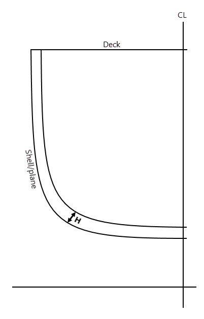
Definition girders and webs, example 1.
Example 2: Web plates A and B are defined separatly, as shown in the picture below. First web plate A:
- Begin point along plane Shell/deck on intersection with CL.
- At that begin point the inside of that web on height TT. For this the intersection of CL and TT is taken which is exactly what we want.
- End point plane Shell/deck on intersection with TT.
- At that end point the inside of that web on height TT. For this the intersection of TT and TT is used, which there are an infinite number off, but in this exceptional situation we will choose the intersection of Sheel/deck which is exactly what we want.
And web plate B:
- Begin point along plane Shell/deck on intersection with TT.
- At that begin point the inside of that web on breadth R1. For this the intersection of TT and R1 is taken and that is precisely what we want.
- End point along platen Shell/deck on intersection with main deck.
- At that end point the inside of that web on breadth R1. For this the intersection of main deck and R1 is used which is precisely what we want.
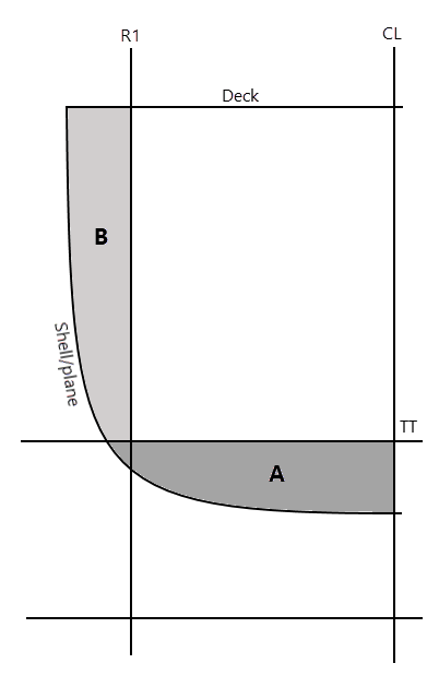
Definition girders and webs, example 2.
Example 3: Finally the construction, pictured below, with a deck and a longitudinal plate which both have been fitted with girders of different dimensions. There are four webs, web plate A is defined as follows:
- Begin point along plane TD on intersection with CL.
- End point along plane TD on intersection with LS0 or LS1.
- Fixed girder height which belongs to A.
Part B:
- Begin point along plane TD on intersection with LS0 or LS1.
- End point along plaen TD on intersection with Shell/plane.
- Fixed girder height which belongs to B.
Part C:
- Begin point along plane LS0 on intersection with Shell/plane.
- End point along plane LS0 on intersection with TD.
- Fixed girder height which belongs to C.
Part D:
- Begin point along plane LS1 on intersection with TD.
- At that begin point the inside of that web (as well as) along plane LS1 on intersection with TD with an offset HD0.
- End point along plane LS1 on intersection with maindeck.
- At that end point the inside of that web (as well as) along plane LS1 on intersection with maindeck with an offset HD1.
Note that the parts A and C partially overlap. This can't be helped because of the design model where by not every detail is been shown. For the benefit of the simplicity of the data definition (and thus the definition speed).
As mentioned before a web can be streched along multiple planes. Take for example; that C&D have a fixed girder height H (and a fixed thickness etc...) this can then be specified as follows:
- Begin point along plane LS0 on intersection with Shell/plane.
- End point along plane LS1 on intersection with maindeck.
- Girder height H.
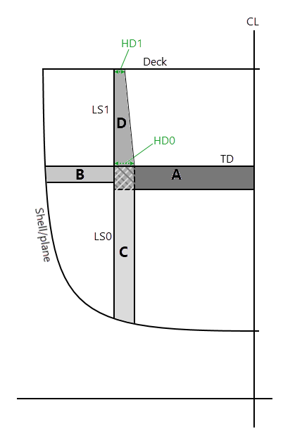
Definition girders and webs, example 3.
Lastly a description on the term ‘Layout-plane’. Such a plane can be used for the definition of the positions of the webs, it's as simple as that. There are no further requirements on the presence or continuity of the planes. This gives a certain freedom which can be used as follows:
- A reference plane. This is simple, they strech along the whole vessel.
- A physical plane, which definitely can be used where it's located.
- A continuous physical plane. In the end a physical plane is nothing else that an infinite plane including a certain closed boundary. Also outside this closed boundary the infinite plane continuous and this can best be used in terms of positioning. For example, the height of a girder can be referenced on the tanktop even in places where this tanktop is not present.
Modus operandi of the PIAS to Poseidon conversion
- Use this Layout option, which creates a text file, with .txt extension (as required for import in Poseidon).
- Gebruik deze Layout optie, waarmee een tekstbestand wordt aangemaakt met extensie .txt (zoals vereist voor de import in Poseidon).
- Start Poseidon, and select File/Open.
- Choose at Files of type: Poseidon TXT File (*.txt).
- Indicate the file just created by Layout.
Ship, layout, plates, girders, webs and stiffeners defined in PIAS, converted to Poseidon.
Design choices, limitations and conditions
The PIAS→Poseidon conversion has, in close collaboration with the leading customer, been designed for this anticipated use:
- Ship data and layout data which are intrinsically present in PIAS must be converted to Poseidon.
- It is the intention of this customer to ultimately manage data of hull, layout and structure from a central design system, and to convert those to Poseidon via PIAS.
- For practical reasons, it was decided that data types not included originally in PIAS (such as deck loads, girders and stiffeners) should, for the time being, be entered in PIAS in simple alphanumeric menus. These input menus lose their role once these data are included in the central design system. That is why these import menus are quite Spartan, and are not equipped with graphical input or feedback facilities.
- PIAS stores these additional Poseidon data in XML format. This makes it possible for that central design system to write out the same data in that format as well, so that they are immediately available in PIAS (and hence for conversion to Poseidon).
- The data that PIAS can supply to Poseidon is sufficient for that first customer with the current implementation. However, there are also things that are not included in PIAS and this conversion, such as pillars, man holes and welding details. For the time being, it is not the intention to extend the conversion with these components, although in specific cases extension can always be discussed with concrete users.
- Obviously, each user is free to supplement or modify the data that is imported from PIAS with the User Interface of Poseidon.
- Attention
- Poseidon‘s interface format has occassionaly very specific requirements and restrictions. In this conversion option of PIAS quite some effort has been put to meet them as much as possible, and the many tests show that the geometry from PIAS transfers rather well into Poseidon. However, in general, a flawless operation in Poseidon is not guaranteed.
On this conversion the following remarks and conditions apply
- This conversion is tested with and valid for Poseidon version 17.0.8, (2018).
- Poseidon is fully dedicated to construction frames, so it is of utmost importance to define the frame spacings properly in PIAS (see Frame spacings), including the position of the aftmost and foremost frames.
- Angled transverse bulkheads are excluded from the conversion.
- For Poseidon it is a prerequisite that frame 0 coincides with the APP (see chapter 2.2 of the Fundamentals manual of Poseidon).
In Poseidon a so-called longitudinal element is bounded by either another element, or the shell. However, in reality these boundaries may changed, for example the lower boundary of a longitudinal bulkhead, which may at the aft side be the tanktop and at the fore side the shell. For Poseidon this bulkhead should be split into two parts; an aft part which is bounded by the tanktop, and a forward part bounded by the shell. PIAS will detect such a phenomenon, and split automatically. However, there is a pitfall which is related to the split location which should be positioned exactly on the intersection between two internal planes and the shell. In our example the intersection of longitudinal bulkhead, tanktop and shell. This point can easily be obtained by interpolation, however, because PIAS and Poseidon apply their own independant interpolation methods it may very well occur that on the split position as determined by PIAS, Poseidon does just not find an intersection between bulkhead and tanktop. In such a case the split position will have to be modified slightly, manually in Poseidon. This phenomenon is intrinsic to Poseidons modus operandi, in particular to the requirement that a longitudinal element must be split, and can in principle not be avoided. However, in practice its occurrence is proportional to the interpolation neccessity, so, it is advised to include in PIAS as many frames as possible, preferably all construction frames (which can be generated conveniently with Fairway).
Write XML file
For the purpose of communication with other software, with this option one may export the ship's subdivision data to an XML file. At present this file contains data of compartment shapes, bulkheads & dekcs and reference planes. This data is limited to that which users have really needed up to now, and includes eg. shapes, names and location of the different entities, but not all the details. E.g. the second compartment name and the sounding pipe are missing. However, if required these data can be added, please also refer to Export to and import from XML. The name of the file written is PIASfilenaam.fromLayout.XML.
Incidentally, these XML data are not only available via a file, but also in direct and permanent comunication between computer programs. In this way, multiple persons can work with different CAD programs simultaneously on the same ship design. More details can be found in a paper, www.sarc.nl/images/pdf/publications/international/2015/Koelman%20Compit%202015.pdf, which has been presented at the Compit'15 conference.
Read XML file
With this function, an XML file with ship's internal layout can be imported into Layout. All comments made in the previous section, on exporting, also apply here. The expected file name is PIASfilenaam.toLayout.XML.
If a file is imported that has planes but not (everywhere) compartments, this will lead to spaces between those planes that are not filled with a compartment. It might be useful to have Layout then generate such compartments. Therefore, the program asks the question ‘What to do with empty spaces between planes’, to which one should then answer appropriately.