In-depth analysis of PIAS
A technical background of the PIAS ship design software and its modules.
Download PDF version
Summary
PIAS, which is an acronym for Program for the Integral Approach of Ship design, is an integrated computer program for ship design. It comprises, among others, modules for the design of hull and internal geometry, and for the computation and assessment of intact stability, (probabilistic) damage stability, longitudinal strength, resistance and propulsion and much, much more.
PIAS can be used in all design stages, from the first preliminary sketch up to the final design, including the related delivery documents. PIAS’ calculations have been approved by major classification societies, and are executed according to the different international regulations, such as IMO, SOLAS and MARPOL.
On this page the background of PIAS is elaborated, and specific functions and options are discussed into more detail.
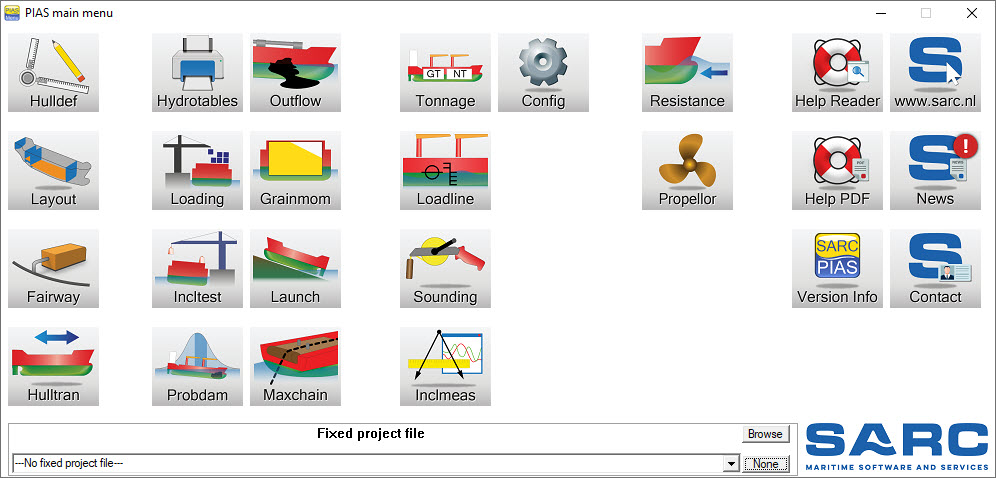
General features
No hull form shape limitations
PIAS has no limitations concerning the shape of the hull form. It can deal with monohull and multihull ships, knuckle lines, a bulbous bow, one or more propeller tunnels, rise of floor, rise of keel or an asymmetric hull form. Besides ships, numerous other floating objects have been defined and calculated with PIAS, such as a floating swimming pool, a 300m floating flood barrier, floating segments of motorway tunnels, offshore barges, et cetera.
Professional calculation methods
PIAS’ advanced and highly accurate calculation methods guarantee an optimized ship design within a short time. PIAS has been approved by major classification societies and statutory authorities.
User friendly
PIAS is written by naval architects; all necessary functions are included, while superfluous gadgets are avoided. Furthermore, quite some research effort is devoted to develop and explore geometric modelling methods, which is reflected in user-friendliness on a level which is more fundamental than the visual layout only.
Modular by design
You only purchase those modules which are actually needed for your business. In-depth details of our PIAS modules can be found below.
Used by shipyards and architects worldwide
PIAS is being used daily by shipyards and naval architects from around the world. In The Netherlands, SARC is the market leader with its maritime software.
Various output formats
PIAS offers a wide range of industry standard output and report formats. Please refer to the Modules page for an exhaustive list.
Continuous development by hands-on experts
At SARC, each employee is involved in both software development and design projects which utilize PIAS. New options are continuously developed, on request of users and when the need arises in-house. This ensures PIAS is always state of the art.
Naval architectural calculations
An outline of available calculation methods is listed below. For clarity, features shared among calculation methods are listed first.
Shared stability calculation features
- Calculation of intact and damage stability can be performed including the effects of the actual transverse and longitudinal shift of liquids. With this method, which replaces
- All calculations can be performed including a static wave, super-positioned on the waterline.
- Where applicable, the effect of submerging of each individually defined opening is taken into account.
- Calculation of intact and deterministic damage stability can be performed including the effects of grounding of the vessel.
Hydrostatics and general stability-related modules
- Hydrostatics for upright, heeled and trimmed conditions.
- Cross curves of stability with the following options: heeling angles up to 180°, constant LCB method, in waves.
- Bonjean curves.
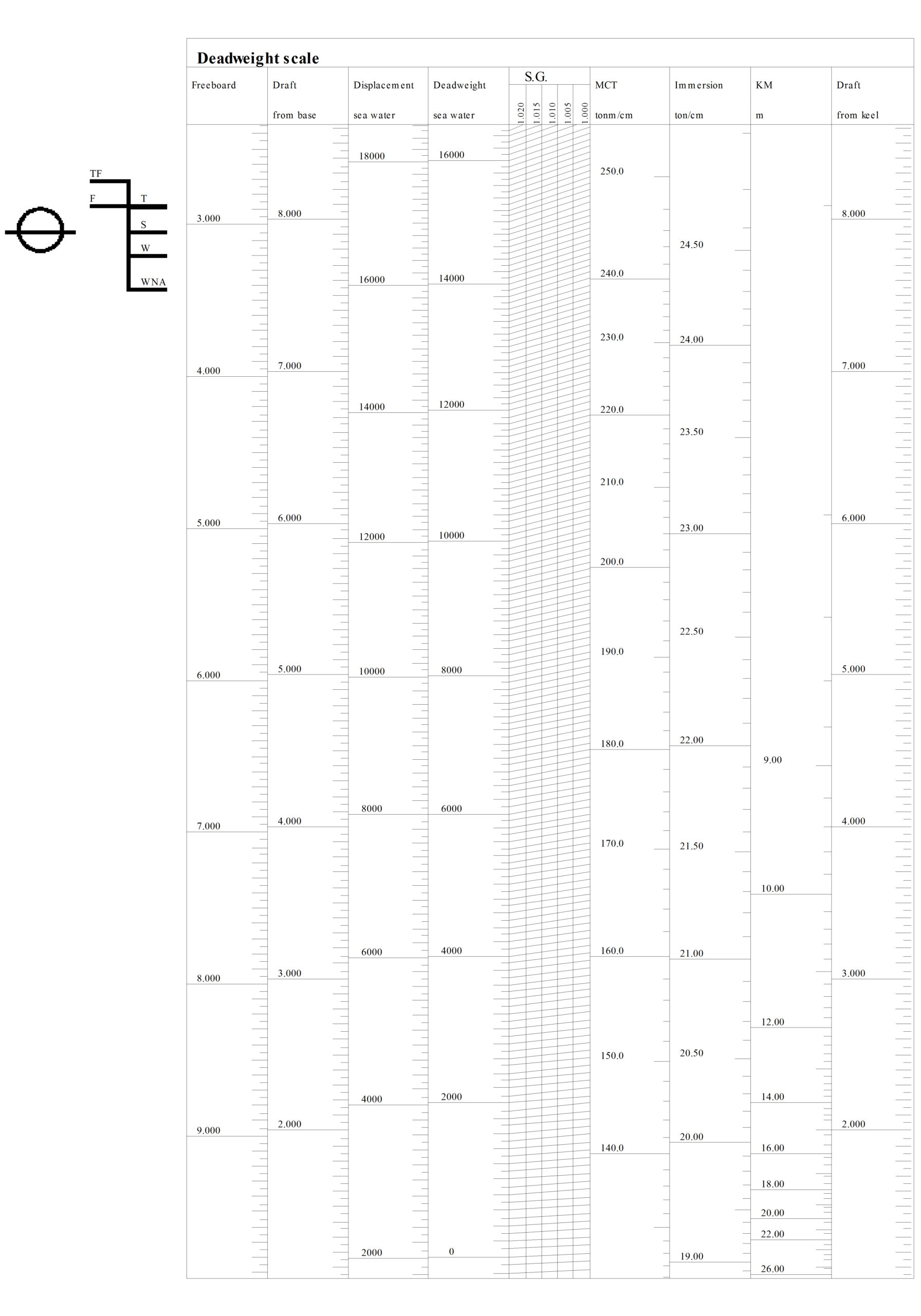
- Tonnage, deadweight tables and deadweight scale.
- Trim diagram according to Van der Ham’s method.
- Tables of tank capacities, containing level, volume, weight, sounding, ullage, pressure, COG’s and FSM’s, et cetera.
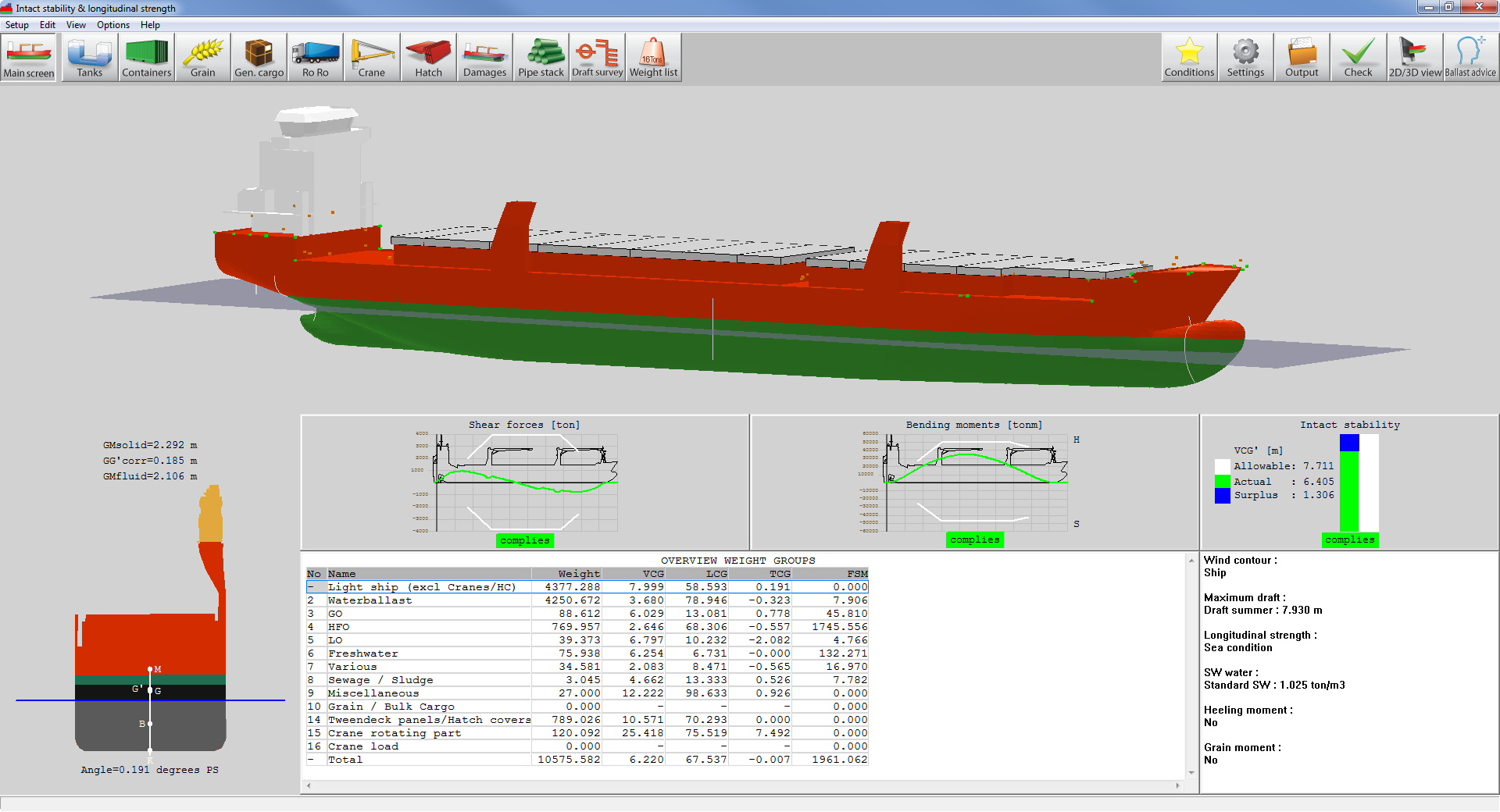
Intact stability and longitudinal strength
Definition of loading conditions, using miscellaneous aids, such as:
- Graphical User Interfaces (GUIs) wherever practicle, such as for tank filling and crane operations.
- A database of weight items, combined with weight items defined separately for each loading condition.
- Multiple options for tank filling (by percentage, by weight, by volume, with a slider).
- Automatic reading of tank sounding tables, based on volume, weight or percentage of filling.
- Automatic generation of loading conditions, to simulate a RoRo operation.
- A crane module, to calculate positions of cranes and weights of loads for pre-defined crane geometries and working conditions (slewing and topping angle, longitudinal position of a travelling crane, et cetera). Also suitable for tandem operations.
Computation and assessment of intact stability:
- Determination of upright hydrostatics, trim, stability and equilibrium.
- Plots of righting and heeling lever curves and tables with hydrostatics under heel and trim, et cetera.
- Including weather criteria of the Intact Stability Code.
- Detailed check against selected stability criteria, and a conclusion regarding compliance with these criteria.
- Plots indicating filling of tanks.
- Calculation of tables of maximum allowable VCG’, based on a selection of more than thirty international intact stability criteria.
Calculation of longitudinal strength:
- Calculation of shear force and bending moments based on the same loading conditions as used for intact stability.
- Sagging and hogging, based on the cross section’s moment of inertia that may vary over the hull length.
- Verification against maximum allowable shear forces and bending moments.
- Deflection.
Specific stability-related and miscellaneous modules
- Grain stability, according to the International Grain Code.
- Inclining test report generator. This PIAS module can also be equipped with an electronic measurement device for angles of inclination, which continuously records the inclination and statistically processes the raw data. Because misreadings are skipped, the G’M is averaged on a longer time span and determined with an objective method, the result is a much more accurate assessment of G’M.
- Stability calculations for container vessels sailing the river Rhine.
- Freeboard calculation.
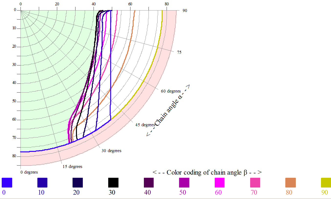
- For anchor handling vessels: maximum allowable anchor chain force, according to the criteria from Norwegian Maritime Directorate 2007 as well as Bureau Veritas 2014.
- Stability calculations for hopper dredgers (including spilling of cargo and pouring in of seawater), according to multiple international regulations, including the ‘guidelines for the construction and operation of dredgers assigned reduced freeboards’ (dr-68).
- Outflow of oil, according to MARPOL 2007.
- Longitudinal launching.
Damage stability
For deterministic damage stability calculations, damage cases are defined by selecting a number of defined compartments. Permeabilities for the ingress of seawater may be set for each compartment separately, as indicated in the applicable regulations. Available functionality is:
- Floodable lengths curves.
- Floodability and damage stability, to determine trim, heel and residual stability in damaged condition, comprising:
- Applied to the same loading conditions as used for intact stability.
- Stability is calculated for the ingress of water into, and the loss of fluids from, damaged compartments.
- Including intermediate stages of flooding, either standard (25%, 50% and 75%) or complex (taking into account flooding through external and internal openings).
- Calculation of tables of maximum allowable VCG’ in damaged condition, based on a variety of international damage stability criteria (including passenger ships, oil tankers, high speed craft, chemical tankers and gas carriers).
- Damage stability, including water on deck (for RoRo vessel, according to Stockholm agreement).
Probabilistic damage stability
PIAS provides one single module for probabilistic damage stability, which supports all present and past regulations: IMO res. A.265, SOLAS 1992, SOLAS 2009, dr-67 and dr-68 (for hopper dredger with reduced freeboard). Besides from the option to perform the calculations in a standard and approximative (zone-based) way, PIAS also offers the options of taking into account a much more exact calculation procedure, based on the real shape of the compartments.
The PIAS methods offer the following advantages:
- Damage cases are automatically generated, which has the advantage that it has become practicable to use more damage cases, leading to a more favorable result (higher subdivision index A).
- Damage boundaries are automatically determined, saving the user quite some time and effort.
- The option to determine the VCG’, in order to attain the index A to be exactly equal to the required index R.
More details of the PIAS approach can be found in the paper ‘A new method and program for probabilistic damage stability’, as presented at the Compit’06 conference.
Hydrodynamic predictions
PIAS offers a number of resistance and propulsion options:
- Resistance prediction for displacement vessels, according to Holtrop & Mennen.
- Resistance prediction for small (< 45 m) displacement vessels, according to Van Oortmerssen.
- Resistance prediction in the pre-planing range, according to Savitsky & Brown.
- Resistance prediction for planing vessels, according to Savitsky.
- Resistance prediction for pontoons according to Holtrop (MARIN).
- Resistance predictions for displacement vessels according to Hollenbach.
- Resistance prediction for low L/B Vessels, according to Çalisal & McGreer.
- Resistance prediction for chine and round bilge hull forms, according to Robinson.
- Propeller calculations for the MARIN B-series (open propellers) and Ka-series (ducted propellers), as well as the Gawn and Au series. Including extensions for controllable pitch propellers.
- Velocity Prediction Program for sailing yachts (VPP). This module calculates the velocity of vessels powered by sails. Resistance and side forces are calculated and used to optimise the sail trim for every wind angle and wind force. The stability and the resistance are calculated using the actual geometry of the hull form.
- Prediction of manoeuvrability (for IMO recommendations). This module estimates the turning-circle-manoeuvre, the zig-zag manoeuvre and the crash-stop-manoeuvre, and compares these values against the IMO recommendations.
Modelling with PIAS
Hull form
Definition of hull forms can be performed in different ways:
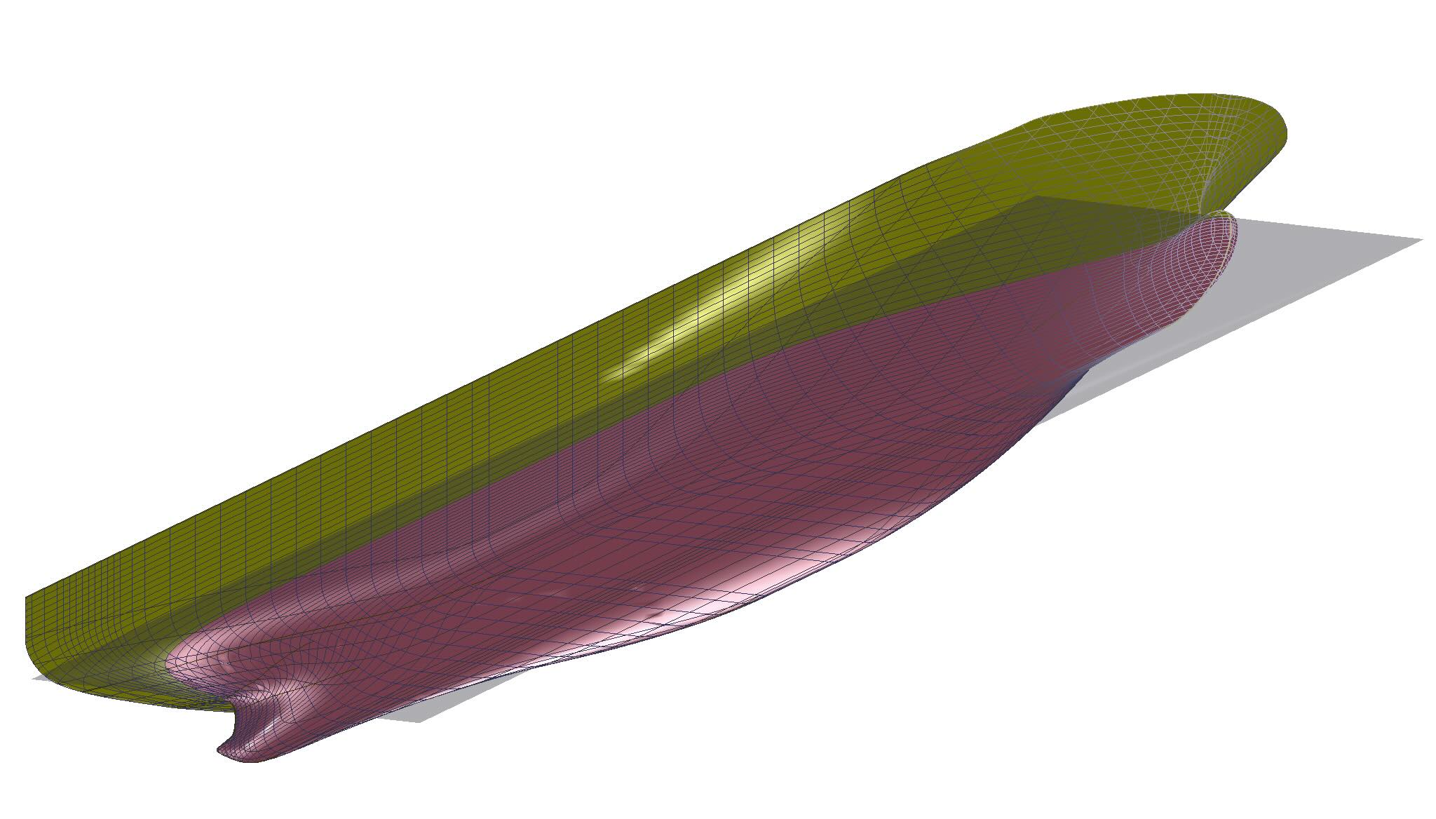
- With the interactive design module Fairway. Fairway is based on an alternative and advanced technology, which makes the existing surface modelling methods obsolete at a strike. See the Fairway page for a discussion of the underlying technology and all its tools and options.
- By digitising cross sections (frames, ordinates) from paper using a digitizer tablet, or from bitmap files displayed on screen.
- Manual definition of an existing body plan, by typing tables of offsets, knuckles and deck heights.
- By hull form transformation. Starting with a parent hull, some parameters (length, breadth, draft, block coefficient, LCB, midship section coefficient and the length of the parallel mid body) can be changed in order to derive a new daughter hull shape.
- Specific tools to define specific elementary shapes, such as horizontal or vertical cylinders.
Internal geometry
Internal geometry comprises the shape and topology of compartments, bulkheads and decks. For modelling of these items, PIAS offers three mechanisms:
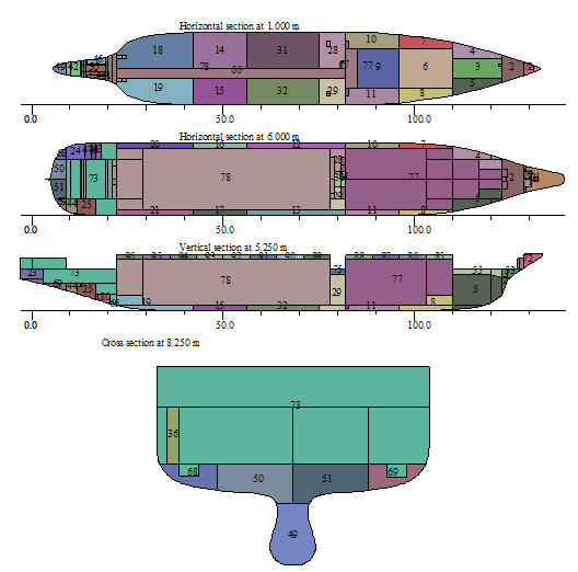
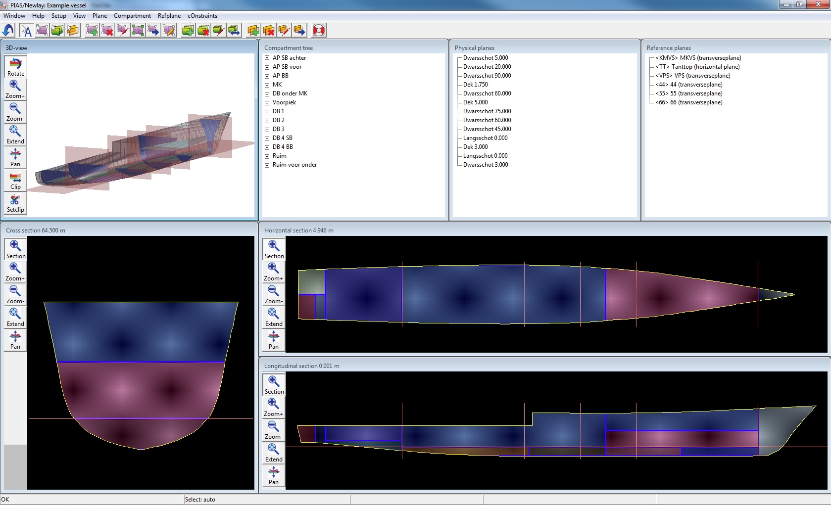
- Once the hull form is defined, all compartment boundaries can be entered. In this process PIAS continuously determines the intersections with the hull, and displays the compartment shape on screen. This what you see is what you get mechanism has proven to be a very good definition and verification tool.
- Positions and boundaries of bulkheads and decks can be entered (or drawn interactively). These planes subdivide the vessel into spaces, which are immediately and interactively visualised. With this method a number of compartments can be defined with a single user action, while subsequent modification can also be done efficiently because the relations between the compartments and the bulkheads or decks are maintained and utilised whenever necessary.
- Compartments with curved boundaries (which are not part of the vessel’s hull), such as the cargo tank of a gas carrier, can be modelled in an alternative way, to enable an exact and easy definition. Any shape defined as PIAS hull form can be used to represent a compartment shape in this fashion.
The first two definition methods may seem unrelated, however, a novel method has been developed and implemented, which ensures compatibility between the two. Further background on this method can be found in the paper presented at the Compit’11 conference.
Furthermore, the geometric definition can be supported by reference planes, which will make design modifications very quick and robust. And finally, auxiliary data, such as names, type of space, sounding pipes (with two pipes for each compartment), pressure sensors et cetera, is co-defined and co-visualized with the compartment shape.
Calculation basis
If the hull form is defined on basis of cross sections, the calculation basis is formed by integration of these sections, and a subsequent longitudinal integration of those integral parameters. However, if the hull has been designed with Fairway a complete surface model is available, which can be visualized and exported.
Import and export
PIAS is equipped with a facility to import ASCII-based tabular frame shape data. Furthermore, hull data can be exported to other ship analysis software, such as for sea keeping, while the internal geometry modelling module has export facilities to Poseidon, the rules program of DNV-GL. Fairway, as being the hull form design module is equipped with additional import and export facilities, such as DXF and IGES, which is discussed into more detail in the Fairway documentation.
Platforms
PIAS is available for Windows 7/8/10 and 11.
Support
PIAS comes with full support for the user. Most user questions can be answered over the phone, but when necessary, models may be exchanged for in-depth support. All SARC employees are actively involved in development, sales, training and project engineering, so expert user support is always available.
Manuals are included with the software, and also available online. New software and manuals can be downloaded from our website, enabling users and their PIAS setups to stay up-to-date with the latest functions and developments.

