This tool is used for defining crane loads. Based on the predefined crane properties, the combined crane load and corresponding COG's are determined. This module for PIAS can be operated from a numerical input sheet, and from a Graphical User Interface (GUI) and for LOCOPIAS only from the GUI.
- Note
- A video exists in which the operation of this module is demonstrated.
Layout
Show and manipulate defined cranes and, if applicable, ballast tanks in a Graphical User Interface, an example of which is depicted below. A description of the labeled elements follows.
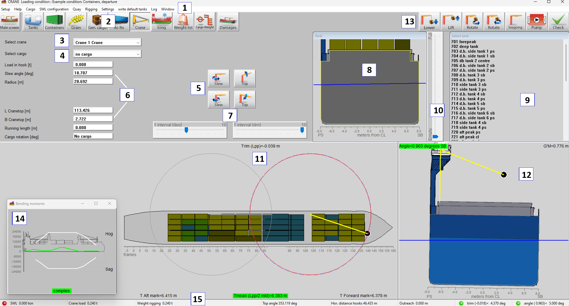
Crane module GUI.
- 1 Menu bar
Basic functions are accessible via the menu bar. In addition to these, the menu bar also provides access to the following advanced functions:
Cargo: Opens the cargo menu window, where each line represents a cargo entry. User is able to define and modify the cargo entries via this menu. Add a new cargo entry with the New option.
SWL Configuration: Safe Working Load. By selecting this option a popup window will open in the main screen. Via this window, the user can select the safe working load table for each crane.
Quay: Define a quay to simulate discharging or loading operations. Its position and dimensions can be visualized in the top and cross view windows via the Quay menu option.
Rigging: Use this menu to set the minimum vertical clearance between the crane tip and the hoisting point, as determined by the rigging configuration.
(Activity) Log: Opens a window on top, in which all crane and ballast operations are listed. This log can be printed. Reset empties the log.
- 2 Module buttons
These buttons navigate to another module, or back to the main screen.
- 3 Crane selection
Choose the crane you want to manipulate.
- 4 Cargo selection
From the drop-down box choose the cargo you want to load.
- 5 Crane operations
Use the buttons to steer the crane or manipulate cargo parameters.
- 6 Crane / Cargo operations
Enter values directly here.
- 7 Interval settings
Set interval step for meters and degrees.
- 8 Tank view
View on the (first) selected tank in a cross section.
- 9 List of tanks
Select a tank for ballasting. For transfer of tank contents between tanks change to the [Tanks] module 2.
- 10 Track bar
The track bar can change the filling of the selected tank.
- 11 Top view
The circles in the top view indicate the maximum and current radius of the crane for the upright vessel.
- 12 Cross section on active crane
In the cross section view the heeling angle and position of the crane can be seen.
- 13 Function buttons
Specific functions to operate the crane, manipulate cargo, pump tank contents and verification of the current loading condition.
- 14 Result windows
Direct verification of stability or strength. This dynamic repositionable window can be activated by the menu bar function [Window]→[Result windows].
- 15 Status bar
- Shows information about the selected crane.
General
On startup of the crane module an input menu, as shown below, is displayed in which crane data can be entered. On exit of the crane module only the selected cranes are added to the list of weight items. During input of crane data a line with hydrostatic information can be displayed at the bottom of the screen. This hydrostatic data is valid for the loading condition including all selected cranes. It is possible to define a maximum of 10 different cranes.
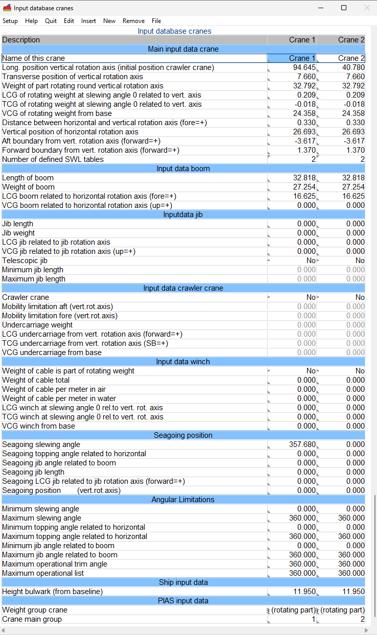
Crane load definition.
In the example above, two boom cranes are defined.
Accidental loss/drop of crane load
If this extension has been purchased, the stability criteria which are applicable after the crane load accidentally drops out of the crane can be calculated. For this calculation you should pay attention to the following items:
- The criteria as usually applicable for this vessel during crane operations should be selected.
- A set of stability criteria as applicable after the drop of crane load must be defined and NOT selected.
- The column ‘loss of load’ must be set to yes for this set of stability criteria.
- Then, if a crane load item defined with the crane module with a weight > 0 is found, calculations for loss of crane load will be executed.
- The loading condition will be calculated twice: first the situation with the load in the crane, secondly the situation without crane load.
- If a requirement is defined including a ‘rollback angle’, the static angle of heel from the first calculation is used for the value of the rollback angle in the second calculation. This statical angle can be set via the variable ‘Heeling angle during lifting’, see Variables.
Menu bar functions
Config
A given set of crane definitions, positions and loads can be stored readily to include it in other loading conditions that use this option. Option [Config] gives an overview of all crane configurations. If a crane configuration is selected (with a ‘yes’ in the first column), the corresponding data will be used. Beware to give the crane configurations unique and unambiguous names, to avoid confusion later on.
Seagoing
Directly set cranes to position as defined (see Inputdata).
Inputdata
The following particulars define the crane and its position:
- Main input data crane
- Name of this crane: The identification name for this crane.
- Long. position vertical rotation axis (initial position crawler crane): The longitudinal distance from App of the vertical rotation axis of the crane.
- Transverse position of vertical rotation axis: The transverse distance from the centreline of the vertical rotation axis of the crane.
- Weight of part rotating round vertical rotation axis: The weight in metric tons of the part that exclusively rotates around the vertical axis. The boom, for example, which also rotates around the horizontal axis is defined separately.
- LCG of rotating weight at slewing angle 0 related to vertical axis: The longitudinal distance from the vertical axis of rotation to the cog of weight of part rotating round vertical axis. Forward of the vertical axis is positive.
- TCG of rotating weight at slewing angle 0 related to vertical axis: The transverse distance from the vertical rotation axis of rotation to the cog of weight of part rotating round vertical axis. SB of the vertical axis is positive.
- VCG of rotating weight: The vertical distance from base to the cog of the weight of the part rotating round vertical axis.
- Distance between horizontal and vertical rotation axis (fore=+): The longitudinal distance between the vertical and the horizontal axis of rotation. The distance is positive if the horizontal axis is forward of the vertical axis.
- Vertical position of horizontal rotation axis: Vertical distance from baseline to the horizontal axis.
- Aft boundary from vert. rotation axis (forward=+): Aft boundary for the purpose of the longitudinal strength calculation.
- Forward boundary from vert. rotation axis (forward=+): Forward boundary for the purpose of the longitudinal strength calculation.
- Number of defined SWL tables: The number of SWL tables that have been defined.
- Input data boom
- Length of boom: Length of the boom of the crane.
- Weight of boom: The total weight of the boom.
- LCG boom related to horizontal rotation axis (fore=+): Position of the lcg of the boom measured along the boom from horizontal rotation axis.
- VCG boom related to horizontal rotation axis (up=+): Position of the vcg of the boom measured perpendicular to the boom from horizontal rotation axis.
- Input data jib
- Jib length: The total extended length of the crane jib, measured from the jib’s rotation axis to the point of application of the load. In case of a telescopic jib, this is the shortest length.
- Jib weight: The total weight of the jib structure, including all fixed elements.
- LCG jib related to jib rotation axis: Longitudinal center of gravity of the jib, measured from the jib’s rotation axis (positive = forward).
- VCG jib related to jib rotation axis: Vertical center of gravity of the jib, measured from the jib’s rotation axis (positive = upward).
- Telescopic jib: A jib with extendable sections, allowing variable length during operations.
- Minimum jib length: Shortest possible length of the jib when fully retracted.
- Maximum jib length: Longest possible length of the jib when fully extended.
- Input data crawler crane
- Crawler crane: A mobile crane mounted on tracks (crawlers), allowing it to move under load in longitudinal direction.
- Mobility limitation aft (vert.rot.axis): Maximum rearward travel distance of the crane, measured from the aft perpendicular (App).
- Mobility limitation fore (vert.rot.axis): Maximum forward travel distance of the crane, measured from the aft perpendicular (App).
- Undercarriage weight: The total weight of the crane’s fixed lower structure, below the rotating part, including tracks or base.
- LCG undercarriage from vert. rotation axis (forward=+): Longitudinal center of gravity of the undercarriage, relative to the vertical rotation axis (positive = forward).
- TCG undercarriage from vert. rotation axis (SB=+): Transverse center of gravity of the undercarriage, relative to the vertical rotation axis (positive = starboard).
- VCG undercarriage from base: Vertical center of gravity of the undercarriage, measured from the baseline of the vessel.
- Input data winch
- Weight of cable is part of rotating weight: Indicates whether the cable weight is included in the crane’s rotating mass calculations.
- Weight of cable total: Total weight of the cable on the drum or in use.
- Weight of cable per meter in air: Weight per meter of the cable when suspended in air.
- Weight of cable per meter in water: Effective weight per meter of the cable when submerged in water (buoyancy-corrected).
- LCG winch at slewing angle 0 rel.to vert. rot. axis: Longitudinal center of gravity of the winch when the crane is aligned at 0° slewing angle.
- TCG winch at slewing angle 0 rel.to vert. rot. axis: Transverse center of gravity of the winch at 0° slewing angle.
- VCG winch from base: Vertical center of gravity of the winch, measured from the baseline of the vessel.
- Seagoing position
- Seagoing slewing angle: With the function Seagoing from the toolbar or in the graphical interface the crane is positioned in position with a slewing angle as defined here.
- Seagoing topping angle related to horizontal: Topping angle of the boom in seagoing condition, relative to the horizontal plane.
- Seagoing jib angle related to boom: Angle between the jib and the crane boom in seagoing condition. This angle is relative to the boom axis (Beam axis is 0 degrees)
- Seagoing jib length: For telescopic jib crane, the jib length in seagoing condition.
- Seagoing LCG jib related to jib rotation axis (forward=+): Longitudinal center of gravity of the jib in seagoing condition, relative to the jib’s rotation axis.
- Seagoing position (vert.rot.axis): Location of the crane’s vertical rotation axis in seagoing condition.
- Angular limitations
- Minimum slewing angle: Smallest allowed horizontal rotation angle of the crane.
- Maximum slewing angle: Largest allowed horizontal rotation angle of the crane.
- Minimum topping angle related to horizontal: Lowest elevation angle of the crane boom relative to the horizontal plane.
- Maximum topping angle related to horizontal: Highest elevation angle of the jib relative to the horizontal plane.
- Minimum jib angle related to boom: Smallest angle of the jib relative to the ship’s boom axis.
- Maximum jib angle related to boom: Largest angle of the jib relative to the ship’s boom axis.
- Maximum operational trim angle: Maximum longitudinal inclination (trim) of the vessel during crane operation.
- Maximum operational list: Maximum transverse inclination (heel) of the vessel during crane operation.
- Ship input data
- Height bulwark (from baseline): Vertical height of the ship’s bulwark measured from the baseline of the vessel.
- Pias input data
- Weight group crane: The weight group (see weight groups: Definition of weight groups) designated category grouping cranes based on weight or capacity for calculation and stability purposes.
- Crane main group: Cranes can have different configurations or variants. For example, a crane having a main hoist position (at the end of the boom) and an auxiliary hoist position, located closer to the slewing axis. Cranes with the same 'main group number' are different versions of a crane at a specific position. If multiple cranes share the same 'main group' number, a selection can be made between these cranes in the GUI.
/note When slewing and topping angle values are changed, longitudinal and transverse positions of cargo are calculated automatically. Vice versa if longitudinal or transverse position of cargo is altered.
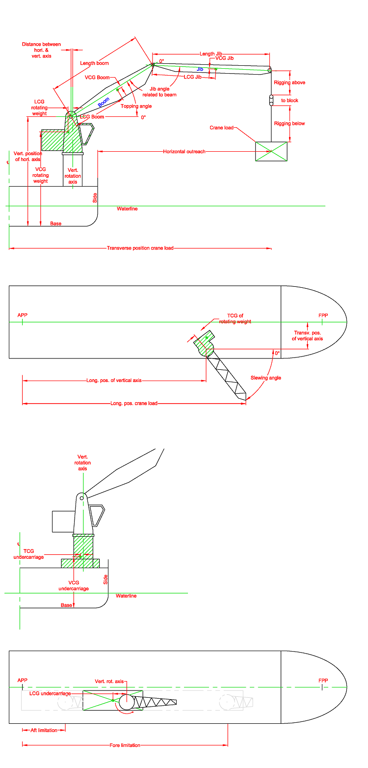
Crane definition aft and top view.