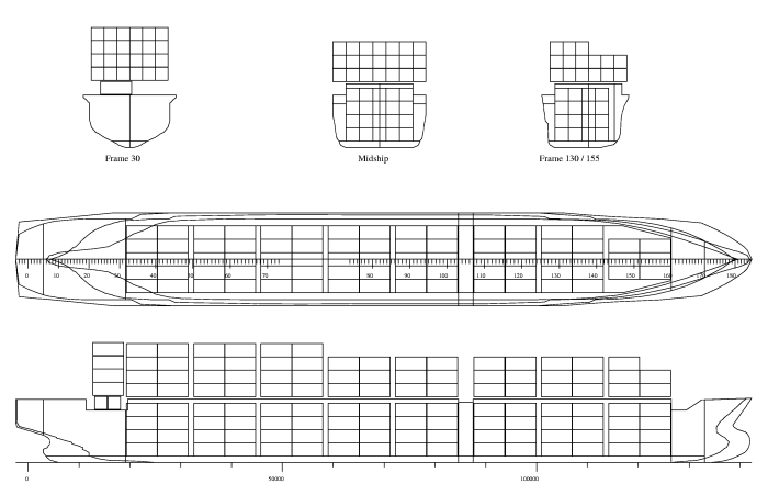
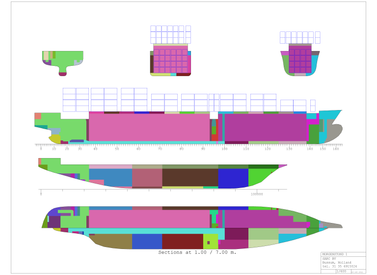
The layout of a two-dimensional subdivision plan can be recorded at this option, two examples of which are displayed above. Such a subdivision plan contains the geometric information of the internal geometry, and can be used as schematic general arrangement plan, tank plan or safety plan. The most obvious application is to have this subdivision plan serve as ‘underlayer’ for such other drawing, and to draw all additions (like deckhouses, masts, lights, valves) in other layers. When the subdivision changes later on, then only that underlayer needs to be replaced, and all other layers can be re-used. By the way, the modus operandi on this subdivision plan is somewhat similar to that of the lines plan in Fairway, please refer to Define and generate lines plan for those details. This subdivision plan section is subdivided into six sub options:
Configuration subdivision plan and DXF export
- Color of the compartments, where can be defined whether any compartment gets an individual color, which is allocated per weight group, or that all compartments are drawn with the same color.
- Desired container slot size, where could be defined which of the predefined container slots should have been drawn in the subdivision plan. The slot size is defined in integer feet, for example 20 or 40. In 2021, PIAS has been refurbished with a completely new container module, and then the display of container positions in Layout was abolished. Upon strong user demand, this could be reactivated.
- Subdivision plan with color. Here is defined whether the subdivision plan is drawn with color or not.
- Draw all, or only the selected compartments. If compartments are specified to be drawn in a section or a view, at this row it can be defined whether all compartments should be drawn, or only the selected ones. This setting only applies to the plot of the plan, not to the 3D-DXF file.
- Coloring compartments in subdivision plan. Here is indicated whether the compartments that are drawn in the subdivision plan are also colored. The alternative is that only its circumference is drawn.
- Additional margin at border (mm). When drawing the subdivision plan on paper, the available paper space is used as much as possible. At this option one can, however, define an additional free space along the paper edge, in millimeters.
- Unit of measurement for the 3D DXF file. Use this setting to specify whether the file dimensions are expressed in meters or millimeters.
- Texts in title block. A subdivision plan that is printed on paper can contain a title block in the right-under corner. This is where you can specify the required number of rows and the text that should be included.
Names and color per part category
This is exactly the same menu as discussed in Names and color per part category, which for the sake of your convenience also has been incorporated in this menu, in order to be able to quickly adjust a configuration.
Subdivision plans layout
The layout of a subdivision plan can be specified here. It is possible to define multiple layouts (maximally four), so that, for example, a subdivision plan with several pages can be defined. When one has chosen this submenu then there firstly appears a window with those various layouts. There is little to say about this, any layout has a name, one can define which one is selected to be drawn. This menu contains a number of specific menu options: HJK2
- [Copy] and [Paste], enabling copying a subdivision plan.
- [Default], which replaces the subdivision plan definition on the current cursor line with a new content using a more or less standard format. Naturally, this layout may not fully meet your requirements, but it can still be useful under the principle that adapting something is easier than reinventing it from scratch. Incidentally, this default depends on the ship's main dimensions, so these must have been entered correctly.
- [Preview], which displays a preview of the subdivision plan as defined on the current cursor line. This function is also available in the deeper-level menus.
With <Enter>, a window opens in which the details of that layout can be defined. Here, you can specify which views are to be included in the subdivision plan drawing and where they should be positioned. The desired location of a section section is defined by its horizontal and vertical offset, expressed in meters. To understand these offsets, imagine that a 2D drawing is first created at a 1:1 scale, with individual views shifted horizontally or vertically by a certain distance in true dimensions (scale 1:1). The scale at which the final drawing is produced depends on the paper size, which is not yet known at this stage, and therefore does not need to be considered here. For each view, the following properties can be specified:
- The shift (offset) in breadth, in m, of this section on the 2D scale 1:1 subdivision plan. This shift has no absolute meaning, but records the relative position of the view relative to other views. It is common practice that one view has no shift.
- Analogous to the previous row: the shift in height, in m, of this section.
- The view, which may be a top view, side view or front view as desired.
- The number of cross-sections that is drawn in this view. When one wants to change this number, one enters a deeper menu.
- Whether an X-axis with dimension ticks marks should be drawn. The options are: no X-axis, plain X-axis, X-axis with dimension ticks marks without legend, X-axis with marks and legend in millimeters, X-axis with marks and legend in meters, X-axis with marks and legend in frame number. This last option is only available at the top and side views.
- Analogous to the previous row: whether a Y-axis must be drawn with dimension ticks.
- The description, that is the name of this view, which is printed below the view.
As mentioned above, after choosing the fourth menu option, you enter a deeper menu, where details of the sections of the view in question can be defined. Per view one can define here:
- The position. At front views in m from App, at top views in m from base and at side views in m from CL, positive for a cross-section at SB side and negative for a cross-section at PS.
- The side. At top views and front views one can define here whether the cross-section is located at one side (PS or SB), or extends over both sides.
- Section/Contour. Here one defines whether it is a real (inter)section, hence a cutting, or a projection, a contour. The following details are applicable here:
- A contour can only be defined for the hull, sounding pipes, piping systems and special points. It makes no sense for other objects.
- At a contour of the hull many points of it are projected in the view plane, and its envelope is determined. Substantial steps in the contour view can be possibly cut as a result. When this occurs, so be it.
- Pipe lines, sounding pipes and special points can perhaps best be drawn in ‘contour’, because they are all shown then. Mostly there is little to see at ‘cross-section’, because the probability that such a pipe or point is exactly in that section is small (although the program uses a certain tolerance around the section).
- Hull. In this column one defines whether the hull must be drawn in the view in question.
- Transverse. Indicates whether transverse bulkheads must be drawn.
- Longitudinal. Indicates whether longitudinal bulkheads must be drawn.
- Deck. Indicates whether horizontal bulkheads (decks) must be drawn.
- Angled. Indicates whether angled bulkheads must be drawn.
- Compart. Indicates whether compartments must be drawn.
- Pipe line, indicates whether piping systems (zie Pipe lines and piping systems) must be drawn. Because the subdivision plan would be much to crowded if all piping systems would be drawn in, in the “regular” plan only the intersections between pipe and desired section are drawn — with a ‘section’ anyway. Subsequently, for all piping systems which are selected with ‘separate subdivision plan per piping system’ a separate plot will be produced, containing the entire subdivision plan plus that single piping system. This only aplies to output on paper or file, not to output on screen. In order to emphasize tge pipe lines in those plots a bit, the compartments are drawn somewhat more pale.
- Sounding pipes. Indicates whether sounding pipes as defined within the compartments (see Sounding pipe) must be drawn.
- Sp.point. Indicates whether the special points of the compartiments (such as openings, see Special points / openings) must be drawn.
- Contain. Indicated whether container slots should be included. This worked with an old format of the container slot definition, which has been replaced by a newer format as used by Cargoquip. Consequently, drawing container slots is now out of order. Upon strong demand from users it could be reactivated.
- Attention
- All physical planes (bulkheads and decks) are being drawn as far as they constitue a separation between compartments, because this gives the most realistic impression. So, this is according to the separating planes on switch which can be defined in the GUI, please refer to View for the discussion. However, this GUI switch has no effect on the plot of the subdivision plan here.
Subdivision plan preview
With this option, the selected layout plan is drawn on the screen. If pipelines have been defined, they are not included in their entirety in the drawing, because with With this option, the selected layout plan is drawn on the screen. If pipelines have been defined, they are not included in their entirety in the drawing, because with a serious number of pipelines this would result in a cluttered image. Instead, intersections between the pipelines and the drawn cross-sectional plane are displayed as markers (provided that the settings, Subdivision plans layout, specify that pipelines should be included in the drawing).
Subdivision plan to paper
The layout plan that was drawn on the screen using the previous menu option can be printed on paper using this option. If pipelines have been defined, and if the settings specify that they should be included in the layout plan, an additional page is generated for each pipeline system, showing the layout plan together with that system. The pipeline system is drawn as projection, however, so it may well extend beyond the cross-sections of the plan.
Subdivision plan to DXF file (2D)
This option generates a DXF file with extension .layoutplan.dxf, containing the selected layout plan. Any pipeline markers are included in the DXF file without explicit dimensions. They are stored as DXF entities of type ‘POINT’, for which a display size can be specified in the CAD system that imports the DXF file. In the DXF, layers are assigned in accordance with the categories defined in Names and color per part category, using the names that can be specified in the rightmost column of that menu.
Subdivision layout to 3D DXF file
Also with this option a DXF file is created, met de extensie .3Dlayout.dxf, which contains the 3D layout model with the following content:
- Lines are of the type DXF polyline.
- Bulkheads and decks are displayed by means of a closed, albeit empty contour.
- Curved or twisted surfaces are first divided in triangles, and subsequently exported as wireframe model.
- Any category, such as hull, decks and piping systems, comes in its own layer, of which you can define its name at [Names and colors per item category], see Names and color per part category.
- Only those elements are included of which at [Names and colors per item category] the DXF column has been set to ‘yes’.