Module
Loading contains many useful tools for exploiting specific characteristics of cargo types or loading tools, such as for container loading, RoRo loading, grain loading and shipboard cranes. All these categories have rather ship-specific features, such as container castings, power connections for reefer containers, decks and lanes for RoRo cargo, attachment points for the lashings of containers and trucks, crane dimensions and capacity, grain bulkheads etc. This is ship-specific input, and it has been considered to give it a place in other input modules, such as
Hulldef or
Layout. However, in order not to overload these modules with options, it was decided to segregate this input into a separate module, called
Cargoquip.
The level of discussion in this module is somewhat more general than in the rest of this manual. After all, by the time the user has arrived at these static ship details, he or she will have gone through the entire cycle of hull and compartment input, as well as performing many calculations. For such a seasoned user, not every menu needs to be covered in great detail. Therefore, the concepts of and relations between the various data will be more important here than the precise menu structure.
- Attention
- Unless stated otherwise, all point coordinates must be given in the PIAS ship axis system.
Input of spaces
In this menu you can define all spaces and their subcategories. You can add any number of spaces, the program will automatically select the necessary ones for every required process.
- Name
- Type a name for the space.
- Compartment
- Press <space bar> to choose from the available compartments defined in Layout. It is not necessary for a space to come from Layout, its cuboid shape can be manually defined in Rectangular cuboid shape definition.
- Decks
- <Double-click left mouse button> or <Enter> in order to add deck data. Refer to Input of decks.
- Panel positions
- <Double-click left mouse button> or <Enter> the cell in order to add panel positions, see Input of panel positions. The panels themselves are defined in Input of panels.
- Type
- Choose between [General] and [IMDG].
- Location
- Choose between [Above deck] and [Below deck].
- Defined
- If the selected compartment has been correctly defined in Layout , then green text "With compartment" will appear and the cuboid shape definition menu is not accessible. Otherwise, the cuboid shape needs to be manually defined. <Double-click left mouse button> or <Enter> will open a new menu to define the cuboid, see Rectangular cuboid shape definition.
Input of decks
In this menu you can define any number of decks that will belong to the selected space. Depending on the type of deck (RoRo or Container), some options might become unavailable. [Duplicate] will duplicate the selected deck, including all its points and settings.
For both types, you can define:
- Name
- Deck type
- Contour points
- Lashing points
For RoRo you can additionally define:
- Floor points
- Ceiling points
- Maximum deck load
- Load allowed : whether RoRo cargo can be loaded on the specific deck
- Line pattern (for drawing)
- Line type (for drawing)
- Line colour (for drawing)
- Line thickness (for drawing)
For Container cargo you can additionally define:
- Castings
- Grid points
- Reefer points
- Maximum stackload for 20ft containers (including types 1,A,B,C,D,E,F)
- Maximum stackload for 30ft containers
- Maximum stackload for 40ft containers (including types G,H,K,LM,N,P)
- Tier offset : The standard offset for containers in the hold is 0. For containers on deck this is 80. Increase/decrease with steps of 2 for a raised/lowered deck.
Deck 3D points
By pressing <space bar> you can connect any point to a reference plane. Not all of these points need to be defined. It depends on the type of vessel, type of space and type of deck.
- Contour points
- Contour points have to be manually defined. The first and last point are always identical, indicating a closed contour line.
- Castings
- Casting points can automatically derive a height from the cuboid shape if the latter has been defined properly. When filling up the castings list, please be aware to include the length and breadth offsets because they will not be automatically added later. You can also Use table to create castings from container slots. The user-defined points in the list will not be affected by the table.
- Grid points
- Grid points can automatically derive a height from the cuboid shape if the latter has been defined properly. A [Bay] and a [Row] also need to be entered.
- Lashing points
- Lashing points can automatically derive a height from the cuboid shape if the latter has been defined properly.
- Reefer points
- Reefer points can automatically derive a height from the cuboid shape if the latter has been defined properly.
Use table
In this table you can input the coordinates of 20ft container slots. New rows can be added by [New] or [Insert] and deleted by [Remove]. New columns can be added by [new Column] and deleted by [remove cOlumn]. The first row is the longitudinal coordinate (LCG), the first column the transverse coordinate (TCG). These coordinates can also be connected to a reference plane. For the height, you can either type the slot underside in the selected cell, or press <Enter> or <Double-click left mouse button> for a popup.
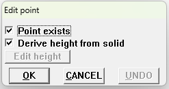
Point manipulation popup.
The slot point can be present or not. If it is, then you can select how the height coordinate is defined: automatically from the cuboid shape or manually. In [Edit height] you can connect the point to a reference plane. If the setting [Derive height from solid] is enabled, editing either the first row or the first column will automatically update the full column or row respectively. When exiting this table, 4 casting points are automatically generated for each existing slot. Please be aware that these 4 points are persistent to their slot and will be re-generated upon every exit of the table.
Input of panel positions
Here you can input panel positions per space. These panel positions will become available to choose from in the Input of panels.
Rectangular cuboid shape definition
If the space is not connected to a compartment from Layout , then for full functionality the cuboid shape has to be manually defined. The cuboid shape is either a rectangular block or a set of merged/connected rectangular blocks. These blocks are defined by 6 points: [Aftside], [Left], [Underside], [Foreside], [Right], [Topside].
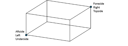
Rectangular cuboid shapes are defined by 2 points.
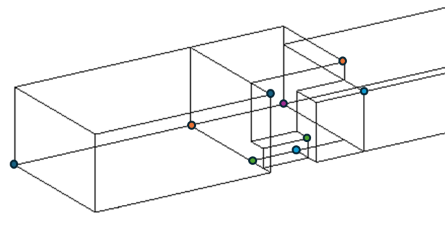
A more complicated shape created by merging. Each pair of points is coloured differently.
If the space is defined by more than 1 cuboid, exiting the cuboid shape definition menu will automatically create the cuboid shape by merging all the cuboids. If the merging operation is successful, the text in the
Input of spaces menu will be green, otherwise red. Cuboid shapes that cannot be created by one or more rectangular blocks have to be defined in
Layout .
Input of panels
You can define all panel data in this menu. The length, breadth and height positions of the panel are given in the PIAS ship axis system.
- Attention
- The axial system of a panel is Aftside, CenterLine, Underside. LCG, TCG, VCG and Castings' coordinates must be given in this local axis system.
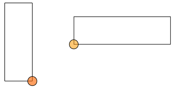
Reference point vertical position (left) and horizontal position (right).
In [Positions], you can <Double-click left mouse button> to select from a list of available positions defined in Input of panel positions.
Input of specific data per cargo type
Locopias configuration settings
Here you can define general settings for :
- Main screen
- Window layout for the Main screen of Locopias. [Use default] in the menubar for a default window configuration.
- Side view colors
- Colors for planes and lines.
- Settings definitions
- Settings to be visible in the main screen : print GM, maximum draught, primsol mark (and its scale factor), XML filename, cross section, maximum allowable heeling angle, side view as 3D.
- Maximum input values
- Minimum and maximum values for (free) weight items in the weight list.
- Submarine control window layout
- Window layout for the submarine control. [Use default] in the menubar for a default window configuration.
- Draft survey window layout
- Window layout for the draft survey. [Use default] in the menubar for a default window configuration.
- Extra lines in 'about SARC' popup
- Enter additional text in the popup window about SARC.
- Bitmap sideview / rear view
- Configure bitmap settings.
Tanks
Here you can define the window layout for the Tanks module by <Double-click left mouse button> in [Number of defined windows]. [Use default] in the menubar for a default window layout.
Containers
- Weight group
- Choose an existing weight group or create a new one.
- Transverse oriented slots present
- If the vessel has transverse slots, set this to Yes. If Yes, there will be an option in the [Settings] of the Container module to turn them on/off.
- Upper side hold
- Fill in the underside of slot for tier 82. You can also press <space bar> to connect this entry to a reference plane.
- Bays above deck, Bays below deck
- It is not necessary to fill up these lists; you can enter one, neither or both, depending on the geometry of the vessel. [Reference point] is a single coordinate, LCG of the bay. [Bay prientation] can be longitudinal or transverse (rotated 90°).
- Rows above deck, Rows below deck
Enter the maximum number of rows. If the number of rows changes from odd to even (or vice versa) then set this to -1.
- Example 1 : bays 01 to 03 have 5 rows, bays 05 to 23 have 6 rows = set this to -1.
- Example 2 : bays 01 to 03 have 4 rows, bays 05 to 23 have 6 rows = set this to 6.
- Note
- The rotated slots are not included in this, ignore them for this entry.
-
If this concerns a vessel without castings, set this to -1.
- Cell guides
- This is currently only used in the lashing module. For the cell guides that occupy 2x20ft bays, please add the bay number on the aft (larger bay number).
- Note
- If you wish for the calculations to take into consideration the cell guides only if there are 40ft containers loaded in the bay, then use the even bay numbering. In the case of a mixed stack (2x20ft together with at least one 40ft) then input the odd aft bay.
- Stepped tank tops
- This is currently only used in the lashing module. Please note that the bay always starts with a 0. Consider stepped tank tops the positions where the bottom of the hold/hatch is at different elevations across the breadth or length of the deck, always 20ft normal height. Other names : tank-top step, stepped hold, raised tank top, elevated tank top.
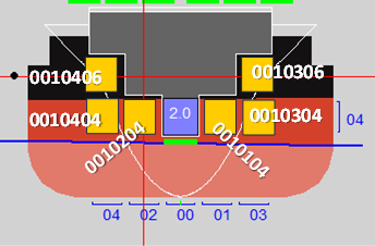
Example : Stepped tank tops shown in yellow for bay 001.
- Number of defined windows
- Window layout for the Containers module. [Use default] in the menubar for a default window layout.
General cargo
- Weight group
- Choose an existing weight group or create a new one.
- Minimum, maximum allowable weight
- Set the minimum and maximum allowable weight for all general cargo.
- Visible compartments in sections
- <Double-click left mouse button> to enter a list of visible compartments in sections.
- Heights
- <Double-click left mouse button> to enter a name and a height for predefined-selection for free placement of cargo in the General cargo module.
- Contour points
- <Double-click left mouse button> to define contour points. Please be aware that the first and the last point should be identical, indicating a closed contour.
- Number of defined windows
- Window layout for General cargo. [Use default] in the menubar for a default window layout.
RoRo cargo
- Weight group
- Choose an existing weight group or create a new one.
- Landing crafts
- Define any number of landing crafts.
Damage control
Use this menu to define and adjust all damage control data.
Definition of countermeasure fill methods
In this menu, set the method type and min/max filling percentages (0–100%) for the following countermeasures groups: ballast, fuel, helicopter fuel, lubricating oil, freshwater, sewage and dryspace. Press <space bar> on a method type to select between: transfer, seawater and transsea.
Definition of countermeasure tanks
Add new tank entries using the [New] option on the toolbar, or select them directly via [Tank List]. Make sure the tank name matches exactly with an existing one. Assign each tank to a group by pressing <space bar> on the group field and selecting from the tank groups defined earlier in the corresponding menu ( Definition of countermeasure fill methods ).
Definition of tank permeabilities
Similarly as in the previous menu, add tank entries by using [New] or select them with [Tank List] option from the toolbar. Then set permeability values for each tank in 3 states: full, partly filled and empty. All values must be between 0 and 1.
Definition of EIB/PIAS cross reference table
Add entries using the [New] option on the toolbar. Type the name and ID of each EIB compartment in the respective fields. To link it with a PIAS compartment, press <space bar> and choose from the available list.
Definition of compartments without internal damage
All available PIAS compartments are listed in this menu. Press <space bar> to select or deselect compartments for inclusion in the damage control file.
Definition of cross-flooding
Add new entries via the [New] toolbar option.
- Cross-flooding name
Type the name of the cross-flooding.
- Countermeasure Group
Press <space bar> to select from the pre-defined countermeasure groups.
- Individual Tank 1, Individual Tank 2 & Combined Tank
Press <space bar> to select compartments from the available list. Each cross-flooding entry must have unique compartments for Individual Tank 1, Individual Tank 2, and Combined Tank.
- Default Situation
- Press <space bar> to toggle between Open and Closed.
Definition of V-line
In this menu, the properties related to stability criteria with a V-line (such as, for example, the US Navy&aposs stability requirements DDS 079-1) can be defined.
Definition of V-line settings
Set the following constants:
- Roll Margin
In degrees (0–50°)
- Wave Height
- In meters(0–50m)
Definition of V-line points adjustment allowed
All V-line type openings are listed here. Press <space bar> to select or deselect openings for inclusion in the damage cnotrol file. If V-line openings have been updated, use the [Read Openings] option on the toolbar to read them again and reload the list.
- Note
- Selecting [Read Openings] will erase all previous selections and set Selected = NO for every opening.
Definition of general settings
Set the following constants (values between 0 and 20):
- dKG0
For the indices ranking formula (in meters).
- FB0
For the indices ranking formula (in meters).
- Min GM
Minimum allowable GM during intermediate countermeasure filling (in meters).
- EIB Critical Stability Boundary
- The EIB critical stability boundary value.
Definition of ultben locations
Define frame data files used in the ultben calculation. Each entry represents one frame. Add entries using the [New] option on the toolbar.
- Frame name
Type the name of the frame.
- File name
Enter the name (without extension), or <Double-click left mouse button> to browse and select the file manually. If the file is in the project folder, just enter its name; otherwise, include the full path. The system will check if the file exists after typing.
- Frame location
Enter the frame’s location (in meters).
- Frame number
- Enter the number of the frame.
- Note
- Frame location and frame number fields are linked. Filling one will auto-fill the other.
Grain
To load grain graphically, it is required to define the geometry of the holds and bulkheads and possible positions. In Layout, make sure you have defined a compartment 1 metre long with the outline of the straight section in the grain hold. If there are also non-parallel sections, you need to define these as a separate compartment. This can be done from the aft/fore of the hold to where it runs parallel again. In the compartment list, you can set the tank to No so it is not counted twice.
- Weight group grain bulkheads
- Choose an existing weight group for grain bulkheads or create a new one.
- Weight group grain holds
- Choose an existing weight group for grain holds or create a new one.
- Tanktop height
- Lower limit of hold.
- Coaming height
- Upper limit of hold
- Movable grain bulkheads
- <Double-click left mouse button> to define any number of movable grain bulkheads. Each grain bulkhead can be given its own name and weight.
- Grain bulkhead positions
- The user can define all possible positions of the grain bulkheads here, both of movable bulkheads and static hold bulkheads. For each position, the following must be entered:
- Position name: The name of the position.
- Bulkhead type: Choice of static aft, static fore or movable. In the case of a fixed bulkhead, only 1 number (rear or front respectively) needs to be entered.
- Aft: The rear of the position in metres.
- Fore: The front of the position in metres.
- Underside: The bottom of the position in metres.
- Topside: The top of the position in metres.
- Breadth: The breadth of the position in metres.
- VCG: The VCG of the movable grain bulkhead above the base in this position.
- LCG: The LCG of the movable grain bulkhead from the APP in this position.
- TCG: The TCG of the moveable grain bulkhead from the CL in this position.
- 'Basis' grain holds
- To define grain holds, they must be available as compartments in Layout. For the part, or parts of the hold that have a simple rectangular cubic cross-section, define a rectangular compartment (hold/metre) in Layout and select this compartment here, where you set the [variable] column to "Yes" and set the length to 1 metre. This compartment is then used for all rectangular cuboid parts of the hold, for which no other compartments are set. If the hold, or parts of it, is not rectangular cuboid, then this part of the hold must be defined separately in Layout. Add these compartments in this menu, and specify the aft and forward boundary of the positions between which this grain hold is to be used.
- Variable: A variable compartment ("yes") is used between all defined positions of the grain hold, for which no other (non-rectangular cubic) hold is defined. It is then usual to define a compartment of the parallel part (hold/metre) with a length of 1 metre. The length of this defined compartment should be specified in the column [length] (typically 1 metre). A non-variable part of the hold is used between the positions specified.
- Name: Here the user can select the relevant grain hold from the compartment list by name.
- Length: If "Yes" is selected for variable, the length of the selected compartment should be specified here.
- Bulkhd. name aft: Here the user can select the name of the respective grain bulkhead position from the list as defined under [Grain bulkhead positions] which selects the rear of the hold.
- Bulkhd. name fore: Here the user can select the name of the relevant grain bulkhead position from the list as defined under [Grain bulkhead positions] which selects the front of the hold.
- Pos. aft: This is automatically filled in after selecting a position in the column "blkh. Name aft".
- Pos. fore: This is automatically filled in after selecting a position in the column "blkh. name fore".
- Startrecord: This is the line number in the grain moments table, where the table of moments for this particular part of the grain hold begins. This is useful if you want to edit or view the grain moments table manually.
- Contour points: A "0" means that no contour has been created. If a contour has been defined, the number of defined points is displayed here. You can click through on this column. You will then get an input menu, in which contour points can be defined. This contour is only used in the graphical interface to display the grain space in the side view.
- Hold(s) excluded for loading of grain
- It may happen that a part of the hold arises between two grain bulkhead positions where it is not desired to load grain with the graphical grain module. These parts can be specified here by specifying an aft and fore position.
- Selection and definition of grain holds
- <Double-click left mouse button> to define void spaces and tables of grain holds defined in ['Basis' grain holds]. For details, refer to Selection and definition of grain holds
Panels
- Weight group
- Choose an existing weight group or create a new one.
Input of IMDG data
- Transverse bulkheads
- <Double-click left mouse button> to enter (length) coordinates for transverse bulkheads.
- Longitudinal bulkheads
- <Double-click left mouse button> to enter (breadth) coordinates for longitudinal bulkheads.
- Decks
- <Double-click left mouse button> to enter (height) coordinates for decks.
- DOC table
- <Double-click left mouse button> to fill in permissible substances per space. In order for a space to appear in this table, it has to be defined as a DOC space in Input of spaces then [Type of space].
Create data files
Cargoquip can generate files that are necessary for the proper functionality of the following modules:
- Tanks
- Containers
- General cargo : main module definition, window layout and panels
- RoRo : main module definition and landing craft
- Grain : graphical grain and grain moments
- Damage control
- IMDG
Import files
Cargoquip can import existing files for easier handling. Unless stated otherwise, all of the properties and entries of the files are automatically added to their corresponding menu.
File and backup management
Backups of all data can be made and restored here. For details, refer to Data storage and backups.