Although Layout was initially designed for defining and visualizing the geometry of internal spaces, it was expanded around the 2020s to include pipeline modelling functions. This created a system that is intended and suitable for:
- Integrated bulkhead/deck & compartment & pipe modelling and visualization.
- Including the effects of pipes on damage stability, and deriving intermediate stages of flooding on basis of the connections between compartments.
- Time-domain damage stability analysis, including the effects of fluid velocity and resistance in the piping networks.
- The exchange of PIAS' piping data with engineering software is still on the wish list. However, due to the lack of a common interface format for this kind of data, this is not expected to become universal.
The piping data structure
For the sake of clarity, the piping-related manual has been split into two parts; the part concerning geometry and compartment connections fits here, in Layout, while the more fluid-flow related part better fits in the chapter on internal flooding in case of damage, see Flooding through ducts and pipes: Consecutive Flooding, after 2022.
The data structure and naming conventions of PIAS' piping is inspired on the ISO-15926 standard, which has an origing in the process industry. The primary elements are:
- Equipment, which is a thing, not being a compartment, connected to a pipe line but not part of it. Such as an engine or a chiller. In the end, PIAS performs no actions with equipment, it is just defined in PIAS for the completeness of definition and drawings.
- A piping system, which is an administrative collection of pipes of the same type, for example “ballast” or “HFO”. Such a system can optionally belong to a weight group — as also applied for compartments and weight items in PIAS, and as discussed in Define weight groups. A piping system can also be assigned a color, e.g. according the ISO 14726 standard.
- A piping network, which is one closed system of connected pipes, which belongs to a piping system. A network is the core of the piping data structure.
- A piping segment, which is one branch of a piping network, and extends between two points without sub-branching inbetween.
- A piping connection, which is a part located at the extremities of a piping segment. Such a connection comes in six types:
- Branch, where multiple piping segments meet.
- Unprotected opening, external (so, to the outside). A nice feature of this type is that such an opening will also be included in the list of openings per compartment (see Special points / openings), as well as the overview menu of openings, List of openings and other special points. In both lists you will be able to change the location of the openings, but for obvious reasons are not allowed to modify other properties or remove the opening.
- Opening + WAPCD (Weathertight Air Pipe Closing Device), vent check valve.
- Terminator, which closes a dead-end segment.
- Compartment, or, more precisely, a connection to a compartment at a certain location. So, a compartment may have multiple connections.
- Equipment, or, more precisely, a connection to a piece of equipment at a certain location.
For each connection also its position can be given, as well as the resistance coefficient, optionally including or excluding the resistance due to the energy loss at the outlet of a pipe (see Fluid outlet energy loss}.
- A piping component, which is a part located in a piping segment. These come in two types:
- Point components, located in a (virtual) point (from which als the coordinates can be given):
- Waypoint, which is a geometrical point without further properties. Can be applied to define the pipe geometry.
- Elbow.
- Valve, including open/closed indication.
- Pressure relief valve, including the opening pressure. An important reason to include this type is for the modeling of fire control bulkheads, which are considered to be watertight until a certain water level (=pressure), and collapse at higher levels. This valve opens inside the pipe, and allows fluid flow in the pipe when opened.
- Reducer, including the regular flow direction (from high to low pressure), as well as the regulared pressure at the exit. Its way of operation depends on the flow direction:
- If the flow is in regular direction, then for the hydraulic calculations the set pressure at the exit is applied.
- If the flow is in the opposite direction, the reducer is assumed to be closed if the pressure at the regulated side (=the original exit) is higher then the set pressure. Otherwise it is open, where the hydraulics arte being computed with calcuthe standard resistance coefficient.
- Check valve (non-return valve), including the free flow direction indicated by an arrow.
- Weathertight Air Pipe Closing Device (WAPCD, Vent check valve) including the free flow direction.
- Pipe components, which exist between two point components. This type has just a single member:
- A pipe section, which is simply a straight pipe between two point components.
Furthermore, for components also their resistance coeffcient can be given as well as their dimensions. Pleased observe that an opening or a WAPCD can be given both as a component as well as a connection. This seems superfluous, however there is a distinct reason:
- As a connection will be used at the end of a segment, typically as a weathertight opening to the outside, for example just above main deck.
- As a component will be used internally in a network, for example a weathertight opening on the vehicle deck of a Ro-Ro ship, covered by the Ro-Ro hold, which in itself is ‘just’ a compartiment in the ship.
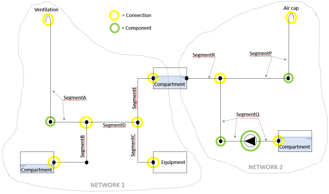
Example of two networks with a number of parts.
With this structure, complex pipelines can be modelled and connected with openings and compartments, as demonstrated by the sketch above. To increase the ease of use, PIAS' pipeline system contains a number of auxiliary functions and concepts that are not essential, but can be useful, such as:
- A complete pipeline definition contains the coordinates of all its parts. Sometimes, however, it will be sufficient to define only the connections, without coordinates. In such cases networks or components can be specified to be without geometry. This can be used, for example, when specifying a standard standard vent right above a tank, in which case the exact location of the connection of the vent pipe to the tank is not important (at least, if one is satisfied that the geometry of the pipeline network is not involved in the damage stability computation).
- A ship model defined without these pipelines will still contain openings and sounding pipes. In the essence, these obviously maintain a relationship with pipelines. To facilitate the upgrading of such a model, there are auxiliary functions to convert these entities to pipelines, see the [Generate] functions in Piping systems.
- For complete flow calculations, the shape, size and resistance coefficient of all pipes and components must be provided. Since in reality there can be considerable uniformity in this respect, these data can also be provided at a higher level, e.g. for an entire pipe system, in order to save typing. This is further explained in Layered definition of flow-related parameters.
The piping's initial menu contains the following options:
The following is worth noting about this list:
- The first two options are a bit duplicative, i.e. that they both provide an entry to the same individual networks. Through the first option, those are grouped by system, and through the second option, a complete list of networks comes up. Both options can come in handy.
- There is additional section with instructions on how to define particularities one may encounter in practice in the ship. However, that is discussed only after the main structure has been explained, in Modelling specific things from the real world.
- There is another place where the pipe lines can be made visible, and that is in the three-dimensional presentation — as discussed in Threedimensional presentation — from which an example is included below.
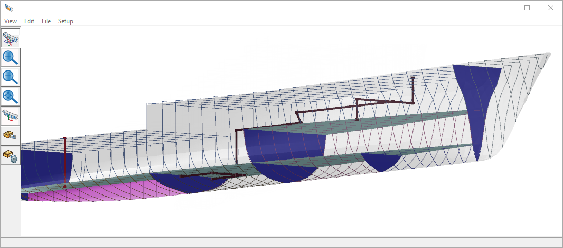
Piping included in the rendered view.
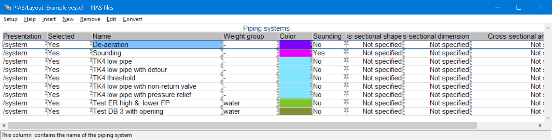
Piping systems
This menu lets you specify a number of properties of pipeline systems. As indicated in the introduction, a system is a collective name for pipelines of the same type, for example “bilge/ballast”. Properties in this menu that need explanation are:
- Presentation, which can be used to specify whether and how the system will be included in the 3D presentation and subdivision plan.
- Selected, which indicates whether this system will be included at damage stability calculations.
- Sounding, which indicates whether pipes of this system are considered to be sounding pipes of compartments. If that is the case then those pipes are automatically added to the sounding pipes of the compartment they are connected to. This is convenient because then those pipes only need to be specified once. In the sounding pipe definition menu of that compartment those pipes will also be visible, but they cannot be changed there.
- For the cross sectional properties of the last columns reference is made to Frictional resistance from pipes lines.
In addition, this menu has three more functions, the first two of which are primarily intended for conversion of older projects (although their use is not necessarily limited to that):
- [Convert / Openings], which, starting from already defined (de-airation) openings of compartments, generates pipelines that contain these openings. This function is clearly intended for the upgrading of elder ship files (with only single locations of openings defined) to a more complete definition which also includes the pipe between compartment and opening. Of course, the generated pipeline shape may need further detailing with elbows or other geometry (because that information was not available initially).
- [Convert / Sounding pipes] is analogous, it converts the existing (loose) sounding pipes of the compartments into pipelines that fit into the integral pipeline system as discussed here.
- <Enter>, which, if the text cursor is on a particular network, takes you one level deeper, to the details of that thereof. Into the piping network menu which is discussed below.
Piping networks
This option opens with the list of networks, like the example below, from which one can be entered for further editing or extension.
List of defined networks, with a number of properties.
The data structure around the pipe lines is sometimes a bit virtual, e.g. a ‘system’ is nothing but an administrative grouping of similar networks. The network, on the other hand, is real; that is a system of pipes into which one can pour water at one end, which can then come out at other ends.
The essence of a piping network is that it consists of segments and components, which can have their interconnections, properties and geometry. On top of that, the network itself has a number of properties, which are accessable through the [properties] menu bar button in the GUI of the figure above, or from the networks list of two figures above. However, that will be discussed later, see Properties of piping networks, first we look at the contents of this GUI:
Piping networks GUI
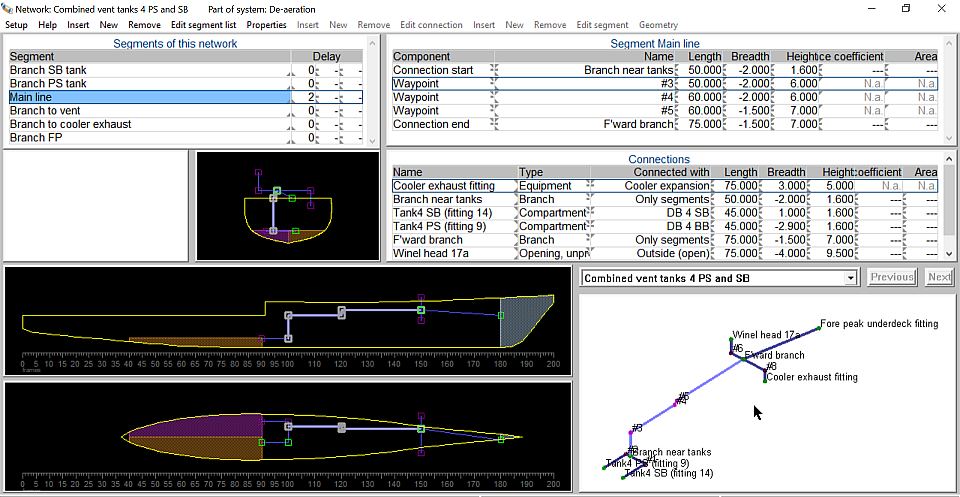
Example of a Piping network, in Layout's GUI.
An example of the specific pipeline network GUI in Layout is shown above. It contains the following sub-windows:
- A list of segments of this network in the top left-hand corner, see Segment list. The segment on which the text cursor is positioned is active in the rest of this GUI.
- At the top right, a list of components of the active segment, see Component list.
- Right centre a list of connections from the entire network, see Connection list.
- The black sub-windows contain the three orthogonal views of the network, including connected equipment and compartments. The locations of these cross-sections are dynamically linked to the mouse position, which works the same way as in the compartment and plane definition GUI, from the first option of the Layout main menu.
- On the bottom right, the 3D view of the network. Here one can rotate, pan and zoom in the usual way.
In the graphic sub-windows, the active segment is highlighted.
Segment list
This sub-window contains an overview of all segments of a network, with their names and their delay factors. The latter are used to generate fractional intermediate stages of filling in damage stability calculations. These are more or less the conventional intermediate stages, as discussed in With conventional intermediate stages of flooding ("Fractional"). At the request of a PIAS user, even multiple such delays can be specified, adding to the variation in intermediate stages. However, those additional delays are optional; for regular use, a single will suffice.
With the segment sub-window selected, a [Properties] function is available in the menu bar. This relates to the entire network of the GUI, and calls the same popup box as discussed on Properties of piping networks. The reason for the presence of this redundant function is that in this GUI it may be handy to see or change network parameters that apply as default to all segments.
Component list
This sub-window shows all the components from the active segment. Obviously, it contains a minimum of two components, which are the references to the connections representing the start and end of the segment. Furthermore, its properties can be specified, such as position, resistance coefficient and cross-sectional area. You can do that by typing those numbers, or using [spacebar] to call a popbox that contains all these parameters. Please recall that for a reliable time-domain calculation not only the cross-sectional area and resistance coefficient of the point components (elbow, WAPCD) must be given, but also of the pipe sections, which should be explicitly specified. For a some types of components, specific properties still apply:
- For a valve, it can be specified whether it is open or closed.
- With a check valve and a WAPDC, the direction of passage is specified. This shows up as an arrow pointing up or down, indicating flow in the direction of the table's row sequence.
- With a pressure relief valve, the opening pressure can be specified. Indeed, two such pressures can be specified specified, one that applies to flow in definition order (which is flow from the component on the top row to the component on the bottom row) and another for flow in the opposite direction. Additionally, it can be specified whether opening of the valve is ‘reversible’ i.e. whether it closes again after the pressure is lower than the opening pressure. A spring-loaded valve will in general be reversible, the collape of a fire-resistant bulkhead not.
Connection list
For the entire network, this list contains all connections, which have types as dicussed on The piping data structure. In the essence, these are the nodes to which segments can be connected to, and which may themselves be connected to another thing, such as equipment, compartment or opening. Actually, there is not much to say about this sub-window, after all, many things like resistance coefficients and so on have been discussed before. Perhaps useful to mention that a connection to a compartment must be completed with a really existing compartment. If that compartment is removed then this connection too will be dead-ending. And perhaps helpful to reiterate that a WAPCD can be specified both with the components and here, with the connections. The difference between the two is explained at The piping data structure.
Warnings on definition errors
This involves a sub-window which will (hopefully) be mostly blank. However, should there be any incompleteness or inconsistency in the definition of a network then it will be reported here. Space here is scarce, so any defect gets only one line. By clicking on that line with the mouse, a popup box appears with, where necessary, a somewhat more detailed description. Should one need an overall list of warnings on all networks, the option from the piping main menu, described at Check the input, can be used.
Some warnings are self-explanatory, while others need some additional explanation, viz:
- When a piping system is declared to contain sounding pipes — which can be set in the ‘Sounding’ column from the piping system overview menu, as discussed at Piping systems — conversion of the pipes defined here to sounding pipes of compartments may occasionally not be possible for a number of reasons, such as:
- The pipe is not located inside a compartment (in other words, none of the pipe ends is connected to a compartment).
- A network contains more than one segment (a sounding pipe may only contain one).
- The number of components in the pipe is larger than the maximum number of sounding pipe points in Layout.
- The number of sounding pipes in a compartment is larger than the maximum of two, in Layout.
In such cases the related pipes can still be used related to their network, for example to play a role in damage stability calculations, however they will not be available as sounding pipes in a compartment.
- “Conflict large cross-sectional area vs. resistance coefficient > 0.”. The Consecutive Flooding system features a setting of the cross-sectional area above which flow is assumed to take place immediate, which is discussed at Minimum sectional area for instantaneous fluid passage. This provides control over the direct overflow of large amounts of ingressed sea water over e.g. a threshold at larger heeling angles of a stability calculation. The actual area of a part is then compared to this maximum, and if greater then the fluid finds no hindrance in the flow. On the other hand, one can also specify a resistance coefficient for a component. If it is greater than zero then the fluid does experience resistance = hindrance, which contradicts the effect of the large area of above. In short, the combination (area > minimum area) and (resistance coefficient > 0) may lead to conflicting results. A warning for this is already given in the definition phase, here in Layout, but it will be obvious that it applies only to the time domain calculation, and not to the fractional method.
- TODO check for other warnings to elaborate upon.
Incidentally, via the top menubar Setup, bottom option, one can choose the topics to be subjected to this check. The same is adjustable in the general pipeline settings, as discussed at General piping settings.
Properties of piping networks
A number of properties are listed in the piping networks overview menu. Via the [properties] menu bar button it opens a popup box with all the parameters of a network:
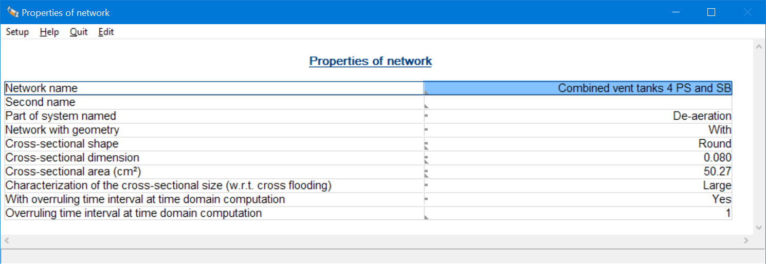
Properties of a piping network.
The non-trivial parameters are:
- Network with geometry. Geometry is the collective name for the coordinates of the components in the network. It will be obvious that a real existing network cannot exist without geometry, and to calculate the flows in the time domain, the coordinates of all components will have to be given. The fractional method, on the other hand, can in many cases quite well without coordinates. To save you typing in parameters that are not used, you can also specify that no geometry should be used. Obviously, the network cannot then be drawn, and the time domain calculation is also disabled. This also offers the choice ‘not specified’, then this parameter is not specified per network, but with the general piping settings, see General piping settings, all created to save you input work.
- Shape, dimensions and resistance coefficient of the cross section. This is discussed in Frictional resistance from pipes lines.
- Characterization of the cross-sectional size with respect to cross flooding. This is a network-level exception on the system wide default as discussed in General piping settings.
- For a time domain calculation, the general calculation time step to be applied can be specified in Config (see Time domain calculation time step). However, for some networks different time step might be desired. That can then be specified here.
Equipment
Equipment does not play an essential role in the piping system. Such a device is simply a designation of an endpoint of a pipe segment, e.g. a generator or a chilled water maker. With the dimensions of the thing included, for the picture and recognition. On a piece of equipment, the pipe stops, so no water flows into or out of it.
Check the input
At Warnings on definition errors it was explained how definition defects are reported per network (while also providing additional explanations about some of the warnings). With this option, these warnings are collected for all networks, in a unified overview.
General piping settings
Here, parameters are defined that are generally used for the pipelines, or for the damage stability calculations that are carried out with them lateron. These are:
- Which network elements will be subject to input control, here in Layout. Possible choices are:
- Only shape and structure of the piping network. This reports e.g. unconnected pipes.
- The same, including specific requirements for the fractional damage stability calculation.
- As 1, including specific requirements for the time domain damage stability calculation. For example the requirement that somewhere in the network some flow resistance should be present (because otherwise, in theory, the fluid moves at an infinite velocity).
- As 1, including requirements for both fractional and time domain calculations.
- Whether networks are with or without geometry. This is a global setting of what can also be controlled at the network level —. the choice is up to the user — and what is explained there at the first option of Properties of piping networks.
- The method of calculating pipe outlet energy losses. There are two conventions for this, i.e. IMO res. A266 & MSC. 362(92) on the one hand, and MSC. 245(83) on the other. A further explanation of this issue can be found in Fluid outlet energy loss. These energy losses have an effect on the time-domain calculation at damage, and one may wonder why this parameter is not located at the damage stability settings. The reason is that this choice determines whether or not explicitly resistance coefficients should be specified for pipe outlets, and this is done here, in Layout. This is why it makes sense to include this general setting in Layout as well.
- Default characterization of the cross-sectional size with respect to cross flooding, a parameter explained in Choice of stability criteria with the fractional method. This is the default, for specfic networks deviating values may be given.
- Default resistance coefficients of components, connections and pipes.
The latter two parameters are components in a chain of flow parameters, as discussed in Layered definition of flow-related parameters.
Output of geometry, connectivity and resistance factors of piping
This option prints all networks — regardless whether the system a network belongs has been selected — on paper (or what the user has set instead), see the example below. As is known, among others, resistance coefficients and cross-sectional areas can be specified on multiple levels, and what is shown with this output are the actual values as they are also will be used in the damage stability calculations. This makes this output suitable to be added as ‘output of the input’ appendix to the calculations, just as is customary for e.g. the input of ship hull shape and compartments.
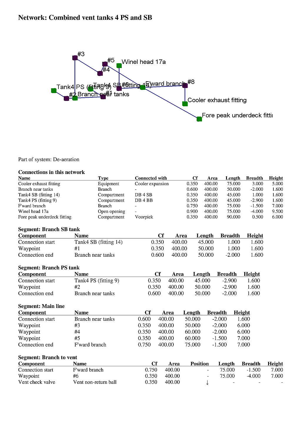
Example of the output of a network input.
Modelling specific things from the real world
How the system as described can be applied to systems of pipelines will be broadly clear, at this stage in the manual. In practice, however, one may encounter ship parts that cannot be immediately recognised as ‘pipeline’, even though they can be modelled as such. For example:
A hole in a bulkhead can be specified as a very short pipe that is connected on both sides to the two compartments adjacend to the bulkhead. In this respect the pipe's position, i.e.nbsp;its longitudina, transverse and vertical coordinates, is determining whether or not the fluid will flow through the hole. The dimensions of the pipe do not play a role in this.
- A ship may be equipped with a fire-resistant bulkhead or door (typically an A60 class), which can withstand a limited level of water pressure. Such a bulkhead can be modelled with just a short pipe, as described above, supplemented by a pressure relief valve in the middle of the pipe. From that valve its opening pressure can be specified, as described at Component list, which for this application is equal to the collapse pressure of the bulkhead. Also, one turns off ‘reversible’ because the bulkhead will not miraculously recover if the pressure drops lateron.
- A demi bulkhead, or a threshold, can be modelled with multiple short pipes at points that are eligible to be submerged as first. See the example below, where three such ‘pipes’ are modelled. The dimensions should then be specified quite large, so that there will be no significant resistance when the fluid overflows the threshold. The exact shape and dimensions do not matter much as these are geometrically are not taken into account anyway.
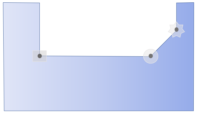
Modelling a partial bulkhead by three short pipes.