Fairway is the hullform modelling module of the
PIAS/
Fairway suite of naval architectural software.
Fairway can be used for any activity with the hullform, such as:
- Hullform generation, both ab initio design and based on a pre-existing shape, in which developable surfaces and doubly curved surfaces may be mixed.
- Design modifications during preliminary design and final design.
- Hullform transformation.
- Fairing with user-controllable accuracy, up to, and beyond production tolerances.
- Generation of shell plate expansions.
- Generation of linesplans and tactile scale models (Rapid Prototyping, 3D printing).
- Import or digitization of hullform data, either complete or partial.
- Perform simple hydrostatic analyses, and farm out complex analyses to the PIAS suite.
- Addition of extra, user defined curves, for example extra frames.
- Export of hullforms, for example to general CAD systems such as AutoCAD (DXF) or Rhinoceros (IGES), to CAE systems such as NUPAS, or to Finite Element or Computational Fluid Dynamics software.
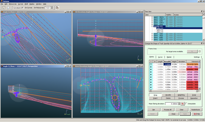
Fairway GUI showing a complex RoRo aft body, with angled skegs.
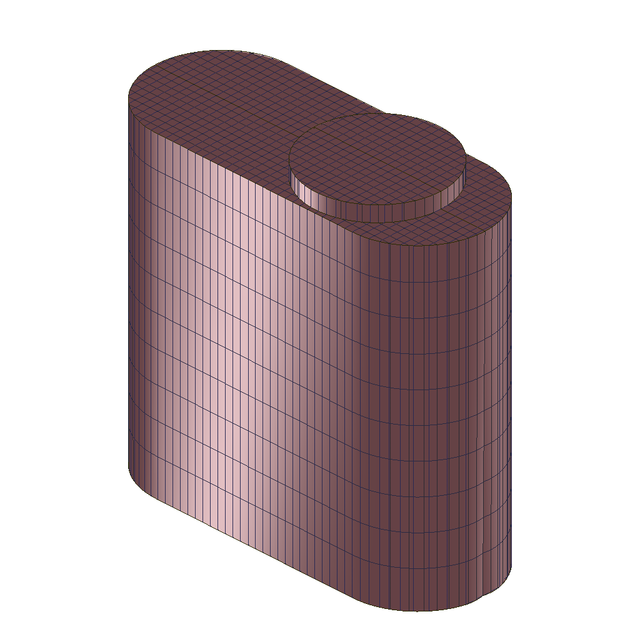
Simple model in Fairway: the trunk of an oil tank.
Introduction
Fairway is a so-called solid modeller,
which is based on a closed 3-D surface model, and wherein the user manipulates the shape of the hull by means of 3D lines, which coincide with the hull surface. As a rule, waterlines, ordinates, buttocks and 3D chines will be used for this purpose, however, the user is completely free to choose those lines which are considered necessary or handy. This introduction starts with a description of some basic concepts, followed by a set of definitions as used in this manual.
Basics of Fairway
- A line consists of one or more concatenated curves. In Fairway this is called a polycurve. The user specifies the nature of the connections between the curves (fair, tangential or with a knuckle).
- Curves are defined as NURBS, and the user can specify the curve type as:
- Spline
- Straight line
- Circular arc
- Parabolic, hyperbolic or elliptical arc.
- Points are defined along the length of a curve. This can be intersection points with other curves, and so-called internal points used to anchor the shape of the curve. An important objective is to keep the distance between points and curves below a certain tolerance.
- The fairness of a curve can be inspected by means of the curvature, plotted perpendicularly to the curve. Curves can be faired through its points automatically with a local scheme, where the user specifies a mean deviation between the original points and the faired curve. The user can also specify the relative weight of each individual point, in three grades: neutral, inactive and heavy. The mean deviation is analogous to the stiffness of the physical spline (the larger the deviation, the stiffer the spline), while the relative weight can be considered as a model for the weights of the so-called ducks.
- Polycurves are connected to each other through the intersection points of point 3, and thereby form a network that describes the hull surface. Contrary to NURBS surfaces, which only exist over a regular network, this network is very shapeable. This is because polycurves need not extend over the full length of the ship, but may be defined where they are really needed.
- Polycurves must start and end at another curve, curve ends cannot dangle freely in space.
- Internally, the network is represented unambiguously with appropriate techniques. Without the use of these techniques a set of curves is ambivalent. Fairway, however, knows about the logical coherence between the points, curves and surfaces, so Fairway does have an unambiguous and correct picture of the object. Together with the methods from points 10 and 11, a solid shape representation is obtained.
- When the program is used for hullform generation, the unambiguous representation is present from the start. When a digitized linesplan is used or a hullshape is imported, the representation will be created automatically. In both cases new curves can be added by intersection with arbitrary planes and other means, they can be manipulated and removed.
- A network of polycurves is termed “consistent” when all polycurves run through their points within the tolerance mentioned in item 3.
- With special techniques, Fairway constructs surfaces over the meshes of the network, based on the shape of neighbouring curves. Areas are automatically detected where it is appropriate to use one surface. The surfaces have curvature in two directions, unless the user explicitly specifies that a surface must be developable.
- Individual surfaces are connected to form a contiguous shell with tangential continuity, unless a curve is defined as a chine.
- In this way a complete, unambiguous surface description is made, on which the following actions can be performed:
- Adding new curves by means of all kinds of intersections.
- Showing threedimensional views, with or without hidden line or hidden surface removal.
- Calculating intersections with other surfaces, or perform boolean operations with other objects.
- The surface is defined by the curves from item 1. If a surface is shaped insatisfactorily, then the network of curves should be adjusted.
- If the tangent continuity from item 11 is not sufficient at some locations, extra curves should be added across that area, which de facto makes the continuity shift to fair.
Geometrical notions
This section deals with a few geometric concepts that are important for using Fairway. No mathematical definitions and backgrounds are involved, just a simple explanation, if necessary illustrated with some graphical examples. Firstly some geometric definitions regarding lines are given, followed by definitions regarding planes.
Lines
- Curve
- A curve is a line segment, straight or curved, without knuckles or cusps.
- Polycurve
- A polycurve is a concatenation of one or more curves. Initially, curves are independent from each other, so there will be a knuckle in the polycurve where two curves meet. By defining boundary conditions one can achieve various forms of transition between curves, which creates a dependency of shape at start- and end-points of adjacent curves. There are six types of polycurves:
- Frames (or ordinates), waterlines and buttocks. Thoese will speak for themselves.
- Diagonals, always with an inclination of 45°.
- Lines in an arbitrary plane. These are fixed in some plane, although not a plane of one of the previous types. With this type also diagonals under non-45° angles can be made.
- General 3D-lines are polycurves which are not fixed in some plane. For example a deck line of a ship with sheer.
The division of polycurves in these six categories is made for the comfort and overview of the user. For the program itself all polycurves are equivalent.
- Knuckle
- A knuckle is a point between two adjacent curves of a polycurve. These two curves are initially independent from each other.
- Chine
- A chine is a polycurve on which crossing polycurves have a knuckle. It is recommended to connect knuckles with a chine. In the Fairway GUI chines are often visualized thicker than other polycurves.
- Spline
- A Spline is a curve which is defined by several angular points called vertices (singular: vertex). The vertices are sometimes called control points, and together they form the so-called control polygon. The curve, as a matter of speaking, is attracted by the control polygon. You might say that the spline is a fair approximation of the control polygon. By changing the vertices the shape of the spline can be manipulated.
- Line direction, left and right
In Fairway a polycurve has a certain direction. For example, the possible directions of a waterline are from ‘stern to bow’ or from ‘bow to stern’. Fairway visualizes the direction of selected polycurves by means of an animation that reminds of waterdroplets that run along the line in the direction of the polycurve.
In relation to this, left and right are defined in Fairway as follows: imagine yourself walking on the outside of the ship, perpendicular to the shell, on the line from the beginning to the end of the line. From this position Fairway’s left is at your left hand, and right at your right hand.
- Radius of curvature
- For each point of a curved line it is possible to imagine a circle which coincides with the line in the considered point. The radius of this ‘fitting’ circle is called the radius of curvature. In the figure the radius of curvature (R) is illustrated.

Radius of curvature R.
- Curvature
- The curvature of a curve in a considered point is defined as the reciprocal of the radius of curvature, 1/R.
- Curvature plot
- In Fairway the curvature is used as a tool for fairing curves. For each point of a line the curvature can be plotted perpendicularly to the considered curve, the curvature plot. A curve can be considered fair if the curvature plot is without unexpected jumps. Two examples are given below. The wild sagging in the left plot is unintended and indicates that the curve is not fair at that location. On the right the plot is discontinuous as is to be expected, between the straight lines (no curvature) and the circular arc (constant curvature).
Curvature plot.
- Moving points
- A point can only be moved in the plane in which the polycurve of the point is defined. A point on a frame can be moved both in vertical and transverse direction. A point on a spatial polycurve can be moved in all directions. For points in which polycurves of different type intersect the following degrees of freedom arise.

Degrees of freedom.
| P1: only transverse motion possible | P4: transverse and vertical motion possible |
| P2: only vertical motion possible | P5: longitudinal and vertical motion possible |
| P3: only longitudinal motion possible | P6: transverse and longitudinal motion possible |
Fairway manages the degrees of freedom and will offer you the available directions of motion.
Surfaces
- Face / surface
- The manual mentions faces and surfaces. A face is the smallest area generated by intersecting lines in 3D space; faces are the meshes of the network of curves. A surface is an area defined by the user, bounded by intersecting lines. A surface can have certain properties, like, for example, developability. No lines can exist within a face. They can exist within a surface, as the surface may consist of several faces.
- Curved surface
- As discussed in the Basics of Fairway, Fairway has the option to create curved surfaces. These derive their shape from the shape of the neighbouring curves. So, there are no handles or functions to manipulate the surfaces, they simply arise between the curves, and the way to influence their shape is by re-shaping the curves in the vicinity. However, there is a single setting for this curved surface creation algorithm, which is discussed just below.
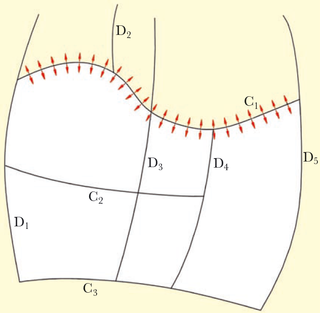
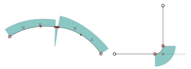
- Tangent ribbon
- As foundation of a curved surface, ribbons of cross-boundary tangents are interpolated. These are the so-called tangent ribbons, which ensure the continuity of the curved shape over the entire surface. These are being constructed on basis of the shape of the curves at all mutual intersections between curves, an example is given in the figure above where the red arrows depict one such a tangent ribbon. This interpolation comes in two flavours, `smooth' or ‘articulated’ at each intersection. In general, smooth tangent ribbons produce a smoother surface, but they can also cause unwanted undulations. In that case articulated tangent ribbons can be selected. Articulated tangent ribbons can be appropriate very early in the design when few curves are present that define the shape, and at the final stage of modelling when many curves are present for construction that give a high number of intersections. The type of tangent ribbon can be set for each solid individually in the menu [Object management].
- Developable surfaces
Developable surfaces are surfaces that are curved in one direction only. They have the advantage that shell plates can be formed without stretch or shrinkage. Conic surfaces are the only developable surfaces. This includes cylindrical surfaces, as these can ge seen as cones with a top at infinity. Two kinds of developable surfaces can be distinguished: single-top cones and multi-top cones. The cones may have any base.
A single-top cone is generated by moving a straight line about a single point in 3D space. This single point is the top of the cone. The straight line is called the ruling.
A multi-top cone can be described as a cone with a shifting top. This top moves along a curved line in 3D space. Each ruling of the cone is a tangent of this curved line at the corresponding top. If a linesplan with developable surfaces is made by hand, the use of multi-top cones is often too complicated. By using multi-top cones it is possible to create complex developable surfaces. When working with Fairway, the user need not to worry about the details of cones and tops, but only indicates the curves that bound the developable surface. Fairway calculates and displays the result, see the figure just below.
A condition for a surface to be developable is that all rulings must exist. A ruling connects a point on one defining line (see below) with a point on the other defining line in which the tangents are coplanar. The rulings are not allowed to cross and no `holes' between the rulings are allowed. This is an indication that the shifting cone top has moved inside the surface boundaries, which is not physically possible. Crossing rulings and holes are illustrated in the figures below.

Forbidden constellation of rulings.
It is not necessary to watch for these defects all the time, Fairway will validate developable surfaces on its own.
- Defining lines of a developable surface
The defining lines of a surface are the two boundary lines inbetween which the rulings run. These lines are called defining lines because only these lines determine the shape of a developable surface. The defining lines must always be chines. No knuckles are allowed on the chine.
If a developable surface is defined by the rulings from a single fixed cone top or if a cylindrical developable surface is defined, only one defining boundary line can be specified.
- Region
- A shell region is a domain on the hull surface, bounded by a closed contour, that may have specific properties. For example, in case of developable surfaces the property is developability. The user can define a region by defining its corners on bounding polycurves. Shell regions are used for e.g. developable surfaces, shell plates — which can be used for shell plate expansions and templates — or to define a phantom face. The modus operandi with shell regions is discussded in Define Shell Region.
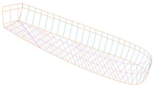
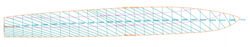
The figures below illustrate a developable surface. The first figure gives a 3D view of a completely developable hull shape. The bottom plate has been selected for processing. The chine and the stem contour are the defining borderlines. You can see the rulings on the bottom plate. The lower figure shows the developed bottom plate.
Solids
When designing the shape of a ship hull it may be convenient to consider the vessel to be composed by multiple building blocks. Such a block can be imagined as a closed and solid bdy, so it will be denoted by the word solid hereafter. In principle each solid is completely independent, and contains its own points, curves and surfaces. Solids can also be imported or exported independently. Also functions are available to glue solids together — e.g. a bulbous bow which is intersected with the hull — however, these are still experimental.
Definitions and concepts
Phantom face
It is important to realize that in Fairway the network of polycurves defines basically a closed surface. This implies that without special provisions the hull will also be closed over deck and over center plane. However, for the sake of clarity polycurves over center plane are by default not generated. This is the result of the center plane and deck region being defined as a phantom plane, which is a face (please refer to Surfaces for its definition) in which newly generated polycurves do not extend. A phantom face can be toggled on or off at any desired moment, see Phantom Faces. However, when toggling the network remains unchanged, so at that moment no polycurves will be added or removed, it only will have its effect on future actions.
There is rarely a need to change the phantom face setting. Only when it is explicitly desired that polycurves do also extend over the center plane, the phantom face has to be switched off. Another case is in the modeling of a deck with one or more hatch openings, then it can be practical to define the openings as phantom faces.
Polycurve visibility
This attribuut nidicates whether a polycurve is visiible in the GUI. The visibility will occasionally also be used at export to other file formats, such as DXF or IGES (when it is asked whether only the visible polycurves should be included in the export). The visibility can be set in the GUI (see Polycurves).
Polycurve locked
A polycurve can be `locked', which comes in two variants, namely `lock against removal' and `lock against removal and modification'. Locking against removal especially comes in handy when working with Polycurve positions sets. For example, when a group of polycurves is added, of which some coincide with the already existing polycurves. When afterwards this group is erased, the already existing will also be removed, which obviously will not be the intention. Locking the original polycurves before adding the groups will prevent this. Locking against modification can be used for extra safety. Especially during fairing, it might prove to be useful to lock certain polycurves which are absolutely not allowed to change. The polycurves can be locked in the GUI (see Polycurves).
Construction Water Line (CWL)
The attribute `CWL' is applicable to polycurves of the type waterline, and indicates which waterline is the `construction water line (CWL)'. The CWL is only applied in Fairway, in graphical presentations (such as those of Show (rendered and colored) surfaces) to show the waterplane and/or to apply differents colors below and above the water surface. The CWL attribute can be set in the GUI (see Properties of polycurves).
Deck at side
Indicates whether this line is a ‘deck at side’. This is only relevant for the conversion of the hull to PIAS' frame model (please refer to Convert this Fairway model to PIAS model for that function), because there the frames from the frame model will be cut off at the level of that deck at side. This attribute can be specified in Properties of polycurves.
Polycurve positions sets
A polycurve position set (prior to 2012 known as a group of line places) is a set of systematic locations for frames, waterlines or buttocks, which can be shown or added at those locations. This mechanism offers the option of some kind of preview, showing polycurves without them actually being added to the model (see Show Indicative Intersections). These groups of locations are managed in a menu which can be called from Position sets. A description of the menu follows below.
- Attention
- A position-set is nothing more than a set of declared positions, irrespective of whether matching polylcurves exist or not. Selecting or deselecting a certain set will not add or remove polycurves at the positions of that set.
- Selected
- This value can be toggled to either ‘yes’ or ‘no’, and indicates whether this set is active in the GUI (corresponds to the check mark in the list of sets in the GUI).
- Name
- This value contains the name of the group. Specifying a clear name may prevent against unwanted adding or removing of lines. A useful name may be something like a short description of the group of lines.
- Line type
- Defines the type of the entire group of lines, the following types can be chosen: frames, buttocks and waterlines.
- minL, minB, minH, maxL, maxB, maxH
- Define the region in which the lines of the concerned group are being added. By means of this function, frames, waterlines and buttocks that do not cover the entire hull shape, can be added. The lines are being cut off on the nearest intersecting line outside the defined domain.
Further definition of a set can be done by clicking it, or by <Enter>. Then a window appears where the following properties can be set:
- Multiple
- This value can be toggled to either ‘yes’ or ‘no’. This specifies whether this definition is appropriate for one line or more than one.
- Beginning cq. location
- This is the first location of the group of lines, or, alternatively, the only location in case Multiple is toggled to ‘no’. The value is the length, breadth or heigth of the first line. Recall that length, breadth or heigth depends on the chosen line type (frame, buttock or waterline).
- End
- The last location of the group of lines.
- Increment
- Defines the distance between each line. This value can be filled in directly, or, alternatively, indirectly by the value number of intervals.
- Number of intervals
- The value is the number of lines which fit between the ‘beginning’ and the ‘end’ with the given increment. Therefore if this value is modified, the increment value is modified automatically, since the beginning and the end are constant during this operation.
Finally, there is a supporting function: if frame spacings have been defined in Config (as discussed in Frame spacings) and a set of frame positions is being edited, then the option [Config-import] appears in the menu bar. This option imports the frame spacings as defined in Config into the current set.
Start and main menu
After starting Fairway, the filename of the project is asked. When you start a new Fairway project, type in the name (and path) for the project. Because Fairway saves a variety of different files, it is a good idea to start in an empty directory. Next the following menu will appear:
The first three options provide the best starting point for a new design, the next steps of which is described in the paragraph below. The fourth option produces a Fairway model from an existing PIAS frame model (in Hull form representations the different hull shape models are introduced). Of such a model the frames are precisely defined, so they will all be included in Fairway. Stem/stern contours and deck line(s) need not be specified in PIAS, so their explicit information is not available. Attempts are made to generate these as completely as possible, but this requires sufficient cohesion in the frames in the vicinity. If stem/stern contour or deck line have an undesired shape then it will need manual adjustment in Fairway (or, alternatively, it can be re-imported with a PIAS form which has been given more coherence by means of more frames).
The fifth option allows the import of a wireframe model, closed hull from a pair of SXF/CXF, as discussed in Import ship hull models in SXF/CXF format and onwards. The import from IGES and DXF produces a set of unconnected curves, as a wireframe. Wireframes can be manipulated within Fairway and converted to solids as described in Wireframes. The detais regarding IGES and DXF are discussed respectively in Import 3D lines from IGES format and in Importing 3D lines from DXF format. When starting with an empty model (last option) the next step would be to create an object in [Object management], as well as defining the design main dimensions, see Main dimensions (design) & hull coefficients.
If "Start with new hull design..." is selected, the following menu will appear:
After entering the main dimensions in this menu, if the first option was chosen, an initial model will be generated by Fairway (with the specified main dimensions), containing one deck line, one stem/stern contour and one frame. With the second option a rectangular barge of the correct main dimensions is created, with the third option a cylinder.
This model is the base for subsequent actions. Values for the block coefficient, LCB and midship coefficient are used as target values for the sectional area curves. These values are not necessarily equal to the final hydrostatic particulars, it is up to the user to achieve those values, with the aid of the controlling mechanisms that Fairway offers.
After the hull is read into Fairway the following main menu appears:
The upper bar of this main menu contains the [Setup] option, which allows general Fairway settings to be specified. Details are discussed in Config: General project configurations. This chapter ends with a set of appendices in Appendices.