|
PIAS Manual
2026
Program for the Integral Approach of Shipdesign
|
|
PIAS Manual
2026
Program for the Integral Approach of Shipdesign
|
The shell of a solid is internally defined as a closed surface. Parts of that surface can be hidden from the eye and omitted during the creation of new polycurves. These parts are called phantom faces. Most hulls that are modeled on just one side of the center plane have a phantom face to hide the imaginary part of the surface that connects the keel line to the deck line inside the hull. See also Phantom face.
Phantom faces can be defined and removed by starting the action from the menu [Shell]→[Edit Phantom Faces], or using the shortcut <Alt><S><P>.
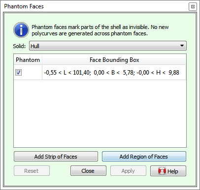
If there are multiple active solids in the model, then the solid of which the phantom faces are to be edited can be selected from the [Solid] pulldown menu at the top of the action panel.
Existing phantom faces of the selected solid are shown in the table underneath, and marked graphically with thick borders in the modeling area. A phantom face can be removed (turned into an ordinary part of the shell) by unchecking its checkbox in the table. The second column of the table contains the coordinates of the bounding boxes of phantom faces, to differentiate them in case there is more than one. Selecting a row in the table will highlight the borders graphically, so the right face can easily be identified.
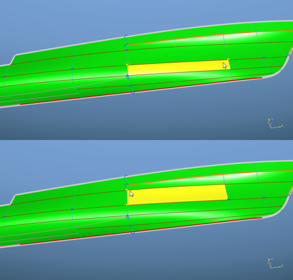
There are two means of adding a new phantom face. A single face can easiest be added by pressing the [Add Strip of Faces] button. This will make the network points of the solid selectable. After selecting a corner of the face in question, only network points on polycurves running through the selected corner become selectable. Hovering over these will prelight faces to the left or the right of the polycurve, allowing you to select the second corner of the same face. This identifies the face unambiguously, and it is marked as a new phantom face. Obviously, this mode can also be used to mark a strip of contiguous faces in one go.
The rule that determines on which side of the polycurve faces are highlighted is as follows: "walking on the outside of the shell along the polycurve from corner to corner in successive order selects the faces to your right." But there is no real need to memorize this because of the visual feedback.
Secondly, faces can be marked in bulk by defining a region of faces, using the button [Add Region of Faces]. This lets you mark the corner points bordering the region in clockwise direction, which should be closed eventually by returning to the start point. For an illustration of this process see the sequence of figures in Definition of a region contour.
Pressing [Apply] will make the specified changes. Note that the action is implicitly reset when another solid is selected from the list, or whenever a solid changes its state of activity in the tree view.