File history
This option is meant to save a set of designs or design stages. It is also possible to use it as a backup option. Maximally fifteen designs can be saved. Apart from the standard editing functions, the option [Select] is also available. With this button you can select a design to work with. When defining a new design with [New] or [Insert], the currently selected design is copied to a new file, for which you must specify a file name. The new design is a copy of the selected design at that moment.
In the menu with design variants one column is marked [Automat. Save]. In this column you can specify which design of the available set is used to save the hullform when the program performs an automatic save action. If the automatic save option is used without a marked design variant, by default the selected design is used for that purpose. The time interval for automatic save is documented in General Fairway settings.
Save current design
The current hull shape is saved without leaving the program.
Object management
- Note
- This menu is also available from within the GUI, by selecting [Solids]→[Object Management...] in the menu bar.
When designing the shape of a ship hull it may be convenient to consider the vessel to be composed by multiple building blocks. These are the so-called solids — from which the purpose and background is discussed in Solids — or wireframes, see Wireframes. These objects are managed in this menu, which contains information as discussed below.
- The first column is used for the selection of solids to take part in Boolean operations, zee below.
- Name. The name of the object.
- Side. The side where the solid resides. The four possibilities are:
- SB. The solid is a half hull, situated at SB.
- PS. The solid is a half hull, situated at PS.
- SB & PS. The vessel is symmetrical over center plane, while the solid is situated at SB, and also models the PS mirrored part.
- Complete. The solid represents a complete hull with a part at SB as well as at PS.
- Active. This cell indicates which solids are active in the GUI.
- Single, a cell which indicates that his solid is single selected for subsequent operations which only act on a single solid, such as hullform transformation.
- Visible. Indicates whether the object is visible in the GUI.
- Locked. If this cell is set to ‘yes’, the solid is protected against any modification.
- Buoyant. If this cell is set to ‘yes’, and if this object is a solid, then it is included in Fairway's hydrostatic calculations. On export to PIAS this switch determines whether this object — solid as well as or a wireframe — will be exported either as added hullform or as extra body.
- PIAS, which indicates whether this object is included in conversion to PIAS' frame model. If a user has the option available, then it can also be specified here that additionally a PIAS triangulated surface file must be created. Details and mechanisms of this conversion are discussed at Convert this Fairway model to PIAS model.
- Main hull. This field is only applicable for objects which have been assigned for export to PIAS. All ‘main hull’ objects are glued one after the other and together form the main hull, the same as is depicted by ‘main hullform’ in Hulldef.
- Linesplan, which determines whether this solid is included in the lines plan, as discussed in Define and generate lines plan. - Export, which determines whether this solid is included in conversion to other (CAD) file formats — such as STL, DXF or IGES — as discussed in Export of hullform.
- Type. For data management reasons some objects are also modelled as ‘solids’. This field indicates the type of objects, possible values are:
- The ship hull, or part of the hull, represented by a solid model
- The ship hull, or part of the hull, represented by a wireframe model
- The Sectional Area Curve.
- A projection line.
- Empty.
- Curved surfaces. Fairway can derive the shape of the surfaces inbetween the curves from the shape of the curves. For this task an interpolation method on the ‘tangent ribbons’ can be set here, please refer to Surfaces for a discussion of this issue.
- Attention
- The columns PIAS and Export govern the export of Fairway's solids and wireframes. The actual execution of such a conversion, and details of their operation are discussed in Export of hullform.
Apart from the general menu bar functions, which amongst other things allow copy and paste of a solid, the menu bar in this window contains a number of additional functions:
- File IO operations of solids and wireframes:
- Export an object. When this option is chosen the highlighted solid or wireframe will be exported to a file, with a user-defined name. The file which is created can be imported into another Fairway project, but it can also serve as a stand-alone hull shape. Note that if master/slave relations were present between curves in this object and other objects, these relations will be removed.
- Import a single object in Fairway format. After specifying the desired file name, the solid or wireframe is imported into a new object. Make sure that the Fairway file to be imported contains only a single object.
- Generation of objects of simple shape. At this moment two shapes are available, a ‘minimal ship’, (which is an object containing a deck line, a stem/stern contour and one straight ordinate) and a 1x1x1 m cube. In due course scaling options and rotation options will be included, in order to give the generated objects the desired size, location and orientation. While these options are still lacking, one can use the ‘hullform transformation’ (see Hullform transformation) to resize and translate objects.
- Functions to combine or divide a hull shape over center plane, ([Centerplane]):
- [Merge]. This function will merge two solids at the opposite sides of center plane. In order to use this function, three conditions have to be met:
- Both solids to merge should contain distinct PS and SB half hulls.
- The two solids must match exactly at center plane. This requirement implies that the vessel must be closed at deck. If that is not the case, the vessel can be closed automatically with a straight deck, see Close vessel at deck.
- Both solids should be selected, and others not. Otherwise the program does not ‘know’ which solids to use.
- [Split]; split a complete hull, which contains both PS and SB, into separate PS and SB half hulls.
- Functions to merge an aft ship with a separate fore ship, or divide a single solid into a distinct aft part and forward part ([Aft+fore]):
- The [Merge] option, which involves merging aft ship and fore ship, which do not necessarily have to be strictly adjacent to each other; if both parts are separated, they will be extended towards the middle, and there connected to each other. The [merge] process is reasonably automated, but it should exactly meet the following conditions (which are as such not very special):
- Exactly two solids should be declared as ‘active’, not intersecting each other, and of which the one entirely located forward of the other.
- On the terminal frames of the two solids — where they are connected to each other, and which we here for brevity baptize ‘midship’ — the solids should have real and complete polycurves of type frame. This frame should extend up to the deck edge, so the lines across the deck and centerplane should not belong to a frame.
- The parts to be merged should each be a half hull, with a phantom face at centerplane, located at the same side (PS or SB).
- The ‘midship’s must not have non-convex faces. Thus, the ‘midship’ as a whole may be non-convex, but must then be divided, for example with waterlines and buttocks into convex faces.
This [Merge] operation results in one new solid where aft and fore are combined. As a rule, this result will have to be postprocessed a bit — for example toggling knuckles or chines, or deleting newly created intersection lines on those locations where the two ‘midship’s had a slightly different shappe — but that can be done with the regular tools of the GUI. In any case, the resulting solid will have a deck line on centerplane, which may be required because the two constituent parts may have a different height at their ‘midship’ sections, so a transverse facet should be placed there in order to bridge this difference. Anyway, if this deck line is redundant it can be removed, that is up to the user.
- [Split], here a longitudinal position can be specified where the single selected solid is to be split into an aft part and a forward part. There is no need for a frame to exist at that position, if this is lacking it will be created. If the assignment of the splitting lines to polycurves is not satisfactory, you can change that in the GUI.
- Boolean operations make it possible to combine two solids in various ways. These solids are marked with the letters \(A\) and \(B\) in the first column, after which it is possible to perform the following Boolean operations: union \(A \cup B\), intersection \(A \cap B\) and difference \(A-B\) (in the menu represented with A+B, A^B en A-B). This way it is possible, for example, to merge a keel with a hull, or construct an open bow thruster tunnel by subtracting a cylinder from the hull, as can be seen in the illustration below. Although the Boolean operations are fully implemented, they are not generally available.
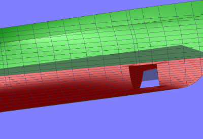
Result of a Boolean `difference' operation.
Quit the program without saving
With this option it is possible to leave the program without saving the design. It deals only with changes in design. Special points, definitions of linesplans, main dimensions and other parameters not related to the form will be saved. To prevent mistakes when using this option, the program asks: “Are you sure?“.