This option is for the visualisation of the model. Sometimes it may be hard to interpret the model from viewing at the wireframe model, it might also happen that surfaces are defined in another way then the user had meant by line modelling. This option is of course also very valuable for making presentations or flyers for the company or the customer. Because of the interactive nature of this menu option, it is less thoroughly described than other menus in this manual.
Unlike the other main menu options, after hitting the <Escape> key the software does not return to the main menu, but generates a rendered image of the model. To return to the main menu without generating a rendered model, use the [Abort] function from the menu bar.
- Drawing type
- One can choose between 'Normal', which means the colors of the area under and above the waterlines have different colors, and 'Shell plate layout', which means every defined shell plate has a different color (see the figure below).
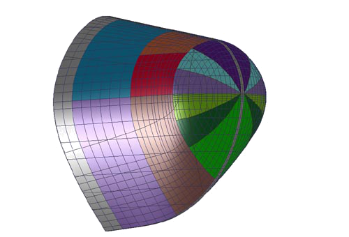
Rendering shell plate layout
- Use "curved surfaces"
- This option defines whether curved surfaces must be used that are derived from the shape of the curves, according to the settings in the right-most column of the menu [Object management]. If this is the case then the surface is triangulated during rendering, up to the detail level given in the setting below. Otherwise coarse triangles are generated between the intersection points in the network of curves.
- Target dimension of planar elements
- This value is an indication of the level of triangularization. A large value may cause the model to look a little rough, while a very small value may cause the computation to take a long time.
- Representation of surface curvature
In the graphical user interface of Fairway, the curvature of a line can be visualised. However, a curved surface is curved in two directions. To visualise the curvature, the curvature in both directions have to be combined to a single curvature parameter. In general, the curvature in the direction of the largest curvature (K1) and the curvature in the direction of the smallest curvature (K2) are combined in one of the following ways:
-
Gausse curvature = K1 x K2
-
Mean curvature = (K1 + K2) / 2
-
Absolute curvature = abs(K1) + abs(K2)
Fairway can determine these curvatures, and present them by means of a color distribution. The examples below show the Gaussian and Mean curvature:
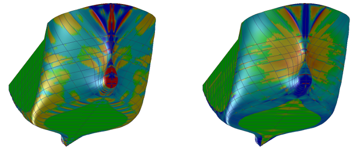
Gaussian curvature (left) and mean curvature (right)
Option in the render window
The window with the rendered view contains in the menu bar a number of functies for setup, printing and export (e.g. to bitmap or VRML format) which are discussed in Rendered views.