|
PIAS Manual
2026
Program for the Integral Approach of Shipdesign
|
|
PIAS Manual
2026
Program for the Integral Approach of Shipdesign
|
The shell of a solid can be partitioned in regions for various purposes. Shell regions are bounded by a sequence of polycurves or sections thereof that form a closed border. The action for defining and modifying regions is started from [Shell]→[Define a Shell Region] or the keys <Alt><S><D>. Regions can be defined for the following purposes:
Most of these purposes can be combined in a single definition, like a shell plate that is also developable, but because plates have a distinct color in order to differentiate them from adjacent plates, plate regions and colored regions are mutually exclusive. Also, export options cannot be combined with shell plates or surface regions — but this is no limitation because in general regions are allowed to overlap. However, overlapping plates are usually undesired and regions with a surface shape property must not overlap.
All regions carry a name.
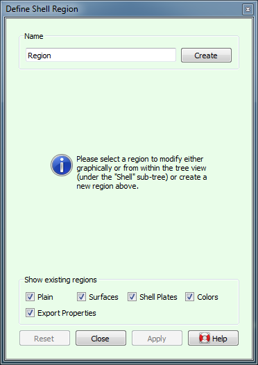
As long as the action is active, existing regions can be visualized by their borders (in bold light gray) and color if applicable. Because regions can serve various purposes and it can be distracting to see regions with a purpose that is not of interest, it is possible to switch their visibility on and off based on purpose with the checkboxes at the bottom of the action panel.
If a region serves more than one purpose, it will be visible as long as any of the corresponding checkboxes is checked.
Regions are defined by a closed contour along (parts of) polycurves that border the region. This contour is defined interactively by clicking in succession on corners of the region in a clockwise direction when looking from outside at the shell.
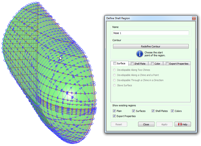
The process of defining the contour is started directly after the [Create] button is pressed, and can be restarted at any time by pressing the [Redefine Contour] button. The first step is to define the fist corner of the contour, and for this any of the network points in active solids can be clicked.
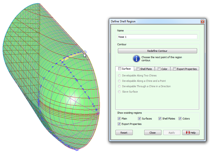
Upon the first click, the start point is marked as such with a halo around it. From this moment on, the only network points that can be selected are the ones that can be reached over the polycurves that cross through the latest added corner. When moving the mouse pointer to the next corner, faces to the right of the path are highlighted, as a visual feedback for the inside/outside of the contour; these faces will form the periphery of the region.
This process is repeated over all intermediate corners. Contours will most commonly be convex, but non-convex contours are supported as well. When points are packed tightly on screen then looking at the last highlighted face will help to determine whether the corner is correctly identified. If at any time a mistake is made and the wrong point is clicked, the process can be restarted by pressing the [Redefine Contour] button.
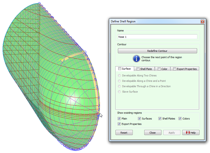
The process is completed by selecting the start point as the last corner, which produces a closed contour.
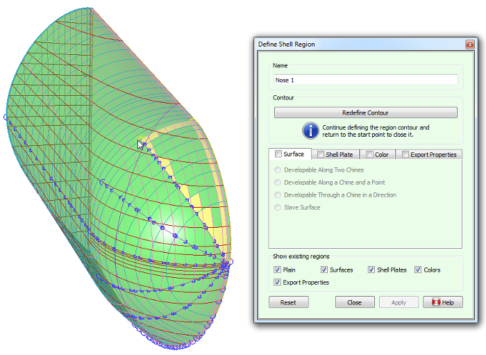
A finished contour is displayed in bold gray curves. At this point the region can be given properties by checking one or more checkboxes in the property tabs.
A region can impose certain shape features onto the curves that it covers, most notably surface developability. Unlinke doubly curved surfaces, developable surfaces have local curvature in one direction only, which allows plates to be formed without stretching or shrinking. The [Surface] tab supports the following types of shape-imposing properties:
Depending on the type of developable surface, its construction requires one or two defining borders, which must be chines and have no internal knuckles. Fairway analyzes the borders and presents the ones that meet these requirements in a pull-down from which they can be selected. Often there is just a single valid option and it will automatically be picked without the need for user interaction. The defining border will be drawn in the developable color (green by default). A defining border can also be selected graphically after pressing the corresponding [Select] button. If the border under consideration does not meet some of the requirements then it will be prelit in the prohibited color (red by default) with a message in the status bar explaining its deficiencies.
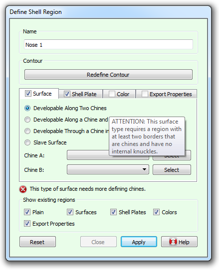
If a developable surface can be constructed, straight rulings will be shown (finely dotted, in green by default) indicating the direction in which the surface has zero curvature. These will remain visible after the action is closed. However, it is not always possible to construct a developable surface for a given configuration, and regions in general can be invalidated as well. When this occurs, a warning message appears in the action panel, describing the problem. Nevertheless, the action will allow any changes to be applied, so that deficiencies may be resolved later. Region validity is discussed in Region Validity.
The region will impose its shape upon affected curves after [Apply] is pressed, as well as whenever a defining border or master curve is changed.
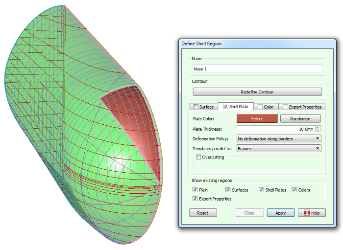
Fairway can generate shell plate expansions and information for the production of shell plating, see Shell plate expansions and templates. A region can easily be marked as a plate by checking the [Shell Plate] tab. (If the checkbox is disabled then the region has probably already a [Color] property. Uncheck the [Color] property, or define a second version of the region.)
The [Plate Color] serves only visualization purposes, to differentiate adjacent plates. If the current plate color does not contrast enough with an existing adjacent plate then a different color can quickly be generated with a click on the [Randomize] button, or selected manually by pressing the colored [Select] button.
The [Plate Thickness] and [Deformation Policy] are relevant for the expansion of doubly curved plates.
In case the production of shell plates requires templates (see Production of templates) the orientation of the templates can be specified using the [Templates parallel to] pull-down.
If the plate needs to be cut somewhat bigger or smaller than the plate contour, then check the [Overcutting] checkbox. This reveals a table in which the overcutting can be specified for each bordering curve individually. A positive value will cause the plate to overlap the adjacent plate (in support of joggling, for example) and a negative value produces an undercutting (to obtain a root opening for welding).
Plate expansions and templates can be generated from [Shell plate expansions and templates] in the main menu.
The [Color] property serves purely optical and presentation purposes. It allows to show regions of the shell with a specific color and transparency, deviating from the overall shell material settings (see Shell). This is the only region that remains visible (without its borders that is) outside region-oriented actions.
Examples for usage of this property include using a different color for the underwaterbody, painting the sheer stripe, fitting transparent windows and windshields, and painting the chimney in company colors.
The [STL Specifics] tab offers two options that are relevant when the hull shape is exported in STL format (see Stereolithography file (.STL) for CFD or 3D printing), in particular when the STL file is intended for CFD analysis. If this tab is unchecked, the global values defined for the export apply to the underlaying shell surface. If the tab is checked, it becomes possible to omit the surface covered by this region from the export, or to specify a [Specific desired triangle size] that will make the underlying surface to be triangularized in the STL export with a triangle size that is different from the global values defined for the export.
The [IGES export patch] tab offers the posibility to fit a single NURBS surface onto a quadrilateral region, if the checkbox in the tab is ticked and the region satisfies a number of prerequisites. All of these regions can then be exported to IGES format using [IGES NURBS regions (2018)]. Connecting borders of incident patches are mathematically equivalent, so that a watertight patchwork can be constructed across the entire shell. The following conditions must be met:
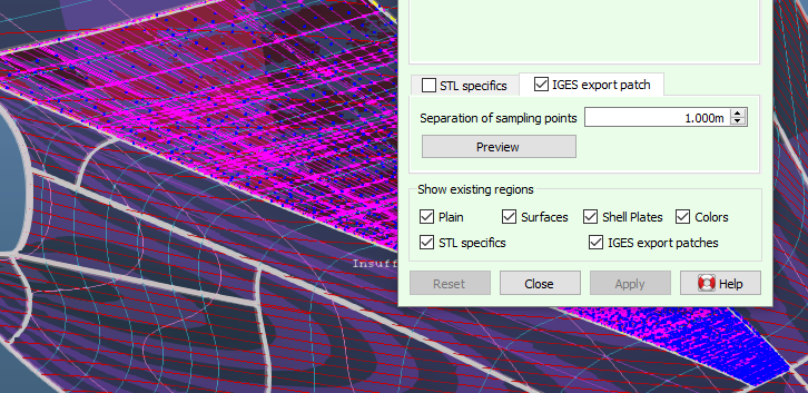
The fitting of the NURBS surface is based on sampling points of the shell surface, the separation distance of which is specified in the input field of the action panel shown above. As a minimum, samples are always taken at every curve intersection within the region as well as in the middle of every face within the region. Pressing the [Preview] button will start the fitting process and show the sampling points in blue, the NURBS control network in magenta (or however the vertex color is configured) and the NURBS patch itself in red. If any sampling points show up in yellow then that indicates that there is a problem with these, which can happen if the third condition above is not met. These points are ignored during fitting and thus a satisfactory result is still possible, but proceed with caution and preferably check the consistency of the curve network and try an alternative region contour.
The time it takes for the fitting algorithm to complete, grows roughly quadratically with decreasing sampling point separation. This means that, for example, fitting with a separation of 0.01m can take 100 times longer than fitting with a separation of 0.1m. Therefore, it is recommended to start out with a large separation, like a tenth or fifth of the longest side of the region which will give a minimal sampling count as explained above, then assess the result and decrease the separation only when necessary. The largest separation that still produces a good fit depends of course on the internal shape of the region: a completely planar surface produces a perfect fit with a minimum of sampling points. The [Preview] button needs to be pressed again to refresh the preview with the new separation distance.
Along the borders of the region, the generated NURBS patch will match the underlaying polycurves exactly, except for a very small affine transformation that cancels out any deviation between the intersecting polycurves at the corners of the patch. This ensures a water tight connection between neighbouring patches. But the internal shape of the patch is an approximation of the sampling points. To obtain high surface quality it is of course important that the curves within the region are well faired and the network has no large deviations (see [Check Solid]) and the finely rendered surface (see [Display]→[Rendering...]) does not show unintended ripples and bulges. But even when all these prerequisites are fulfilled, it can happen that the fitting algorithm produces a patch with erratic undulations over smaller or larger areas of the patch. This is likely caused by an unfortunate distribution of sampling points, which can be resolved by changing the separation of sampling points slightly up or down. In other cases, it helps to adjust the contour of the region, for example by splitting the region in half. For this reason, a careful inspection of the preview is important, with a focus on the NURBS control net (magenta).
Although this functionality can produce IGES export surfaces of much higher quality than the automated output of pre-2018 (see [All faces to IGES NURBS patches]) it involves the manual partition of the shell surface into four-sided regions as required by the IGES standard, while also taking care not to violate the remaining two conditions presented above. This may not always be a straightforward task. When necessary, it may be possible to cover a three-sided area by placing one corner within one of the sides, producing a so-called degenerate corner. This works best where the side has highest curvature and the surface is flat. For example: If a transom stern has one side along the deck line, one along the center buttock and one along the aftmost frame producing three corners, the fourth corner of the region may be placed in the kim of the frame. Othertimes one may need to cover a five-sided area, for which one may choose to add an extra polycurve connecting one of the corners with a point on the opposite side, producing two four-sided regions (see [New Planar Polycurve by Intersection]). Even areas that do have four corners can benefit from being split into smaller regions if opposite sides have very different lengths, in order to prevent NURBS control points from being very tighly packed in the narrow end which can reduce smoothness due to limited floating point accuracy.
Clearly, the definition of regions depends on a particular state of the underlaying curve network. Instead of prohibiting relevant changes in the model, Fairway retains complete freedom and validates the correctness of regions at appropriate times. If, for example, the removal of a polycurve removes the support for one of its borders, the region will be marked as invalid with an icon in the tree view, and a tool-tip will explain what the problem is. In this example the problem can be resolved at any time by opening [Define Shell Region] and redefining the contour with the correct borders.
Changes in curve shape also have the potential to invalidate developable surfaces along two chines; as well as the ability to heal them. As explained in Surfaces, rulings connect two points on opposite defining borders where the tangent vectors are co-planar. If there is too much twist among the defining borders it may happen that no rulings exist that satisfy these conditions. If this is the case, Fairway will complain with a message like "Could not construct a developable surface that contains the current defining chines [...]". The solution is to change the shape of the defining curves and reduce twist.
Another problem is when corresponding points do exist on opposite defining borders but their order is not synchronous. In this case, rulings are generated but they cross or split, and it actually means that the moving top has moved inside te region contour — a situation that is not physically possible. Fairway detects this condition, marks the region as invalid and shows the rulings in the prohibited color (red by default). In practice, this is likely caused by one or more bending points in one of the defining chines that is not sufficiently reflected in the other.