This menu lists all plates that are currently present in the model. Shell plates are defined in the GUI as ‘shell region’ — a notion that is discussed in Surfaces — see for guidelines Define Shell Region. The first column of this menu indicates whether the plate is selected or not, the second column contains the solid and plate name, the last column shows whether the region is valid or not. Valid plates may be selected for generating plate expansions and template information.
- Warning
- Before generating plate expansions, make sure the model is defined accurately enough. The distance between points and curves must be less than 1 mm. See [Make all curves consistent].
Processing the current plate
Whether a plate is selected or not, if the text cursor is on a valid plate then that plate can be processed using the following menu items:
- [Plate expansion]→[Current plate]→[On Paper and/or file] brings op the dialog for output of tables and drawings of the expansion of the current plate, see Production of plate expansions.
- [Plate expansion]→[Current plate]→[On Screen] shows a preview of the expansion of the current plate on screen.
- [Templates]→[Current plate] brings up the dialog for output of tables and drawings for the production of templates for the forming of the current plate, see Production of templates.
Processing selected plates
Depending on the state in the leftmost column, selected plates can be processed using these menu items:
- [Plate expansion]→[Selected plates on paper and/or file] brings op the dialog for output of tables and drawings of the expansions of selected plates, see Production of plate expansions.
- [Templates]→[Selected plates] brings up the dialog for output of tables and drawings for the production of templates for selected plates, see Production of templates.
Production of plate expansions
After selecting any of the above menu items for plate expansion, the dialog below configures the output.
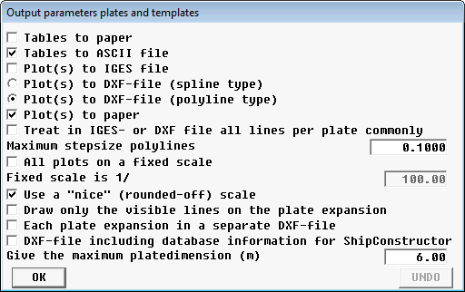
Configuration of output of plate expansions.
- Check [Tables to paper] to print out the tables with expansion information on the selected print device. This output also contains any warnings and error messages, see Warnings and error messages.
- Check [Tables to ASCII file] to write out the tables to a textfile with extension
.XTB. This file will also contain the plate weight, center of gravity and the approximate cutting length.
- Check [Plot(s) to IGES file] to generate a file with extension
.IGS containing the expanded plate with hull lines in the format of IGES type 126 (NURBS curve).
- Check [Plot(s) to DXF-file (spline type)] to generate a DXF file containing the expanded plate with hull curves in NURBS representation. This file can be imported in Autocad version 14, but unfortunately version 2000 (and subsequent versions) contains a serious bug. Its consequences have been discussed in All lines in 3D to AutoCAD DXF-NURBS format.
- Check [Plot(s) to DXF-file (polyline type)] to generate a DXF file with curves in DXF's polyline format, which is essentially a chain of short straight line segments.
- Check [Plot(s) to paper] for a hardcopy of the shell plate expansions on the selected print device.
- When [Treat in IGES- or DXF file all lines on the plate commonly] is checked, the individual curves of a shell plate expansion are grouped together. Both in IGES as well as in DXF parlance such a structure is called a `block', and the advantage can be that when shifting the plate expansion the whole plate is picked up, and not only loose lines.
- The [Maximum stepsize polylines] is, by approximation, the greatest length of the straight line segments of a polyline in meters at scale 1:1. Note that adjacent line segments may be situated exactly on a straight line, in which case these segments will be merged and the final segment length will consequently be greater than the value specified at this option.
- With [All plots on a fixed scale] the scale at which all expansions will be drawn on paper can be specified. If this option is deselected each plate will be drawn at an individual scale.
- If the above option is not checked, checking [Use a "nice" (rounded-off) scale] will result in the use of a scale that is practical for measuring, e.g. 1:10 or 1:25. When unchecked each plate fill be printed page-filling.
- If [Draw only the visible lines on the plate expansion] is checked then hidden polycurves will not be drawn on the expansion plot. Otherwise all polycurves in an expansion will be plotted.
- If [Each plate expansion in a separate DXF-file] is checked then a separate file will be created for each shell plate. Otherwise all expansions will be collected in the same file.
- The option [DXF-file including database information for ShipConstructor] adds additional information to the DXF-file with the expanded shell plate, such as plate area and COG's. Also, with this option an additional DXF-file will be created that contains the (approximate) three-dimensional shape of each shell plate.
- With [Maximum plate dimension] the maximum size (in meters) of an expanded shell plate can be specified. If the option [Each plate expansion in a separate DXF-file] is not selected, this information is used to determine the mutual distance of the expanded shell plates in the resulting IGES or DXF file.
Warnings and error messages
The output of tables with expansion information should be checked for the occurence of any of the following messages:
- The maximum number of edges for the expansion is 2000. This plate has ….
- This message indicates that the maximum number of face edges is exceeded. This shouldn't be confused with the number of border curves in the contour of the plate. In this context the number of edges refers to the total number of edges of all faces which appear in the plate under consideration.
- The maximum number of points for the expansion is 2000. This plate has ….
- This message indicates that the maximum number of points in a plate is exceeded.
- Two points of the plate coincide. No expansion can be made.
- This message is considered to be self-explanatory.
- In line … a deviation between point and line of more than 1 mm occurs.
- This message indicates low accuracy, but the expansion process does continue. However, the results must be suspected!
- In line … between the points … and … the line is not a geodetic. The length difference amounts …%. It is advised to give the line more support with an additional line.
- A part of the expansion process is the subdivision of the plate in triangles, with geodetic curves as sides. A geodetic curve is the shortest line, over a curved surface, between two points. When a low number of points is present in the plate, it can be that the edges of the triangles are not geodetic. You can improve that situation by the inclusion of one or more lines in the neighborhood of the coordinates which are printed in this warning. After this warning the expansion process continues, but the results should be treated with suspect.
- The number of points on the plate is …. That is more than the maximum of 1000. The plate expansion is produced, albeit not optimized for minimal deformation.
- This message indicates that although the number of points in a plate is smaller than the absolute maximum, it is still too large for minimization of deformation.
Production of templates
Templates aid in the forming of shell plates to get the shape right. Templates run parallel to one of the main planes, configured when the plate was defined, see Definition of a shell plate. An additional longitudinal template connects the others at a given angle.
The options for output of template information are mutatis mutandis equal to the ones which apply to the shell plate expansion discussed above, Production of plate expansions.
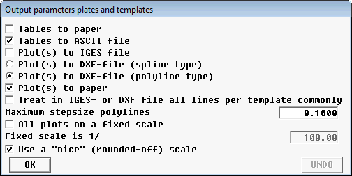
Configuration of output of templates.
Position and shape of templates
Each template has a name identical to the name of a polycurve on the shell plate expansion, which fixes the position. To aid the orientation of the template relative to the shell plate, as well as the orientation of the shell plate relative to the vessel, each template features a cut-away and a chamfer. The cut-away of 25 × 25 mm at the upper side is for aligning the templates, and to provide support for the longitudinal template. The chamfer at one side of the template is helps orienting the template and shell plate in relation to the vessel: If the templates run parallel to frames then the chamfer is located furthest from the center plane. Otherwise (templates are parallel to waterlines or buttocks) the chamfer is oriented in the direction of the fore ship.
The upper sides of all templates for the same plate are coplanar. That plane is chosen such that it minimizes the area of the templates, providing a minimal height of 100 mm, and therefore is seldomly co-planar with one of the main planes.
If the option [Tables to ASCII-file] has been checked, coordinates of the templates will be written to a .tpl file, in mm. All templates of the same plate are defined in the same coordinate system. The height is measured from the top of template and the breadth is measured from a certain reference line. A fragment of a .tpl file can look like this:
Line : Frames    400   Location : 0.400 m
           X      Height      Angle
       100.7       130.5         89
       156.0       133.0
       211.3       134.3
       266.7       134.4
       322.0       133.1
       377.3       130.4         89
       239.0       134.5            (Longitudinal template)
These coordinates can be set out to yield the dimensions of the template as in the figure below.

Coordinates listed in the tables define the dimensions of the template.
The angles listed in the tables define the angle (in degrees) between the plane of the template and the formed shell at both ends of the template. In case templates run parallel to the frames, this angle is set out aft of the template; If the templates run parallel to the waterlines then the angle is set out underneith the template, and if they run parallel to buttocks then the angle is set out on the inside of the template.
The tables are concluded with four additional values, illustrated in the following figure:
- The length of the assembled framework of templates(A)
- The length of the longitudinal template (B)
- The angle between the longitudinal template and the other templates, measured in the plane through the upper sides of all templates (C)
- The angle between templates and the plane through the upper sides of all templates, measured in the plane of the longitudinal template (D)

Framework of assembled templates.