With this option the hullform can be converted and exported to a format suitable for use in other software.
How the conversion is done will be discussed below, and
what will be converted depends on the setting per solid in the menu
[Object management], as follows:
- Aimed at the PIAS calculation modules (which apply PIAS' frame model and occasionally the triangulated surface model) the solids and wireframes will be exported which are selected in the PIAS column.
- All exports to CAD file formats (such as DXF, STL or IGES) include the solids which are selected in the Export column of this menu. The intention is that, in due course, the lines plan will also be exported via this column, but this feature has not yet been implemented.
- Attention
- It is recommended to read On production fairing before using any of the options from this menu.
Convert the Fairway surfaces to PIAS' frames model
From each object which is selected for PIAS in the menu [Object management] all frames are converted to PIAS' frame model — please refer to Hull form representations for a discussion of the different hull shape models. The converted hullform can be used for all functions and calculations in PIAS. At this conversion, the following mechanisms are applicable:
- In the solid properties menu, three columns are important for this conversion. The column PIAS indicates that an object is converted, the column ‘main hull’ indicates whether the object is part of the main hull form. If that is not the case then the column ‘buoyant’ at ‘yes’ indicates that it is an added form, and at ‘no’ that it is an extra body. All of this in accordance with the categories in Hulldef, see Hullforms and Extra bodies.
- More than one object can be classified as ‘main hullrsquo;. In this case, those are sorted in longitudinal direction, and forwarded to PIAS one after the other. This feature is strictly intended for a hull shape consisting of several independent objects that do not overlap in a longitudinally — such as stern - nave - foreship. If objects nevertheless overlap, Fairway will produce a wrning on that, however, it is up to the user to correct.
- A PIAS frame model must meet a number of conditions, such as those listed in Frames (frame positions and frame shapes). It is the responsibility of the user to observe these rules, Fairway does not check for them.
- To pias' frame model, those lines (=polycurves) are converted which are classified as ‘frames’ in Fairway. So, it is not sufficient for a line de facto to be a frame — because its coordinates share their longitudinal positions — it actually needs explicitly to be from this type.
- Once upon a time all the frames present in a Fairway solid were converted to frames model. Occasionally, that proved to be somewhat inconvenient with frames which did not extend over the entire hull body. Such as an auxiliary ‘frame‘ which only did exist in the bilge area, or a tiny ‘frame’ just existing far above the waterline. For PIAS is based on longitudinal integration of ordinate areas, and as such tiny ‘frames’ have little to no area, they induce a fault in the correct sequence of ordinate areas, and to correspondingly incorrect volumes and stability results. But that's all past; frames are only converted to PIAS only if they extend over the entire hull surface. This ‘entire hull surface’ is interpreted as the surface which is bounded at the edges by a phantom face (see Phantom face for an introduction to this concept). It is good to be aquainted with this background, for if Fairway frames are missing in the PIAS model, then it is advisable to check whether in Fairway these are at the bottom and the top indeed connected to a phantom face (which will by default be the case).
- Parts of frames adjacent to a phantom face are not being converted to PIAS. In order to avoid that lines over CL or at the ship's extremes along the deck are included in PIAS&apos frame model.
- If longitudinal polycurves, such as waterlines or 3D lines, are present which have the property ‘deck at side’ then the PIAS frames will be cut of at the level of this line or these lines. Please also refer to Deck at side.
- It is advised to verify the resulting frame model thoroughly with Hulldef.
If you use the local cloud (for which reference is made to Local cloud: simultaneous multi-module operation on the same project), the frames do not neccessarily have to be converted to a file, because at any moment the PIAS equivalent of the Fairway hull form is available through the cloud.
If in the solid properties menu it was specified that a solid should also be converted to PIAS' triangulated surface model, then such a file is also created with this menu option.
Export to DXF and/or IGES file standards
This option allows files to be generated in the widely used CAD file formats DXF and IGES. The following options are available:
2D or 3D
It is assumed that 3D export is the most commonly used export mode in Fairway. However, some users have expressed a need for views in which the 3D geometry is projected onto the three principal planes. When 3D is selected, the resulting file contains a single representation of the 3D geometry. With 2D, the resulting file contains three representations of the geometry, in front, side, and top views. Each view is placed in a separate layer, named after the corresponding view. Note that the origins of these views coincide at (0,0). As a result, the view representations will generally overlap when displayed simultaneously. Since each view is stored in a separate layer, they can be repositioned easily within the CAD system if required. The purpose of this option is to provide the geometry to the CAD system in a neutral form, allowing all subsequent formatting and drafting operations to be carried out within the CAD environment. If more control is required from within Fairway, for example to define the positions of sections and axes or to add annotations, the Lines Plan Export option can be used (see Define and generate lines plan, which also supports output in DXF format.
File format
The output format can be selected as IGES, DXF, or both. A limitation applies to the IGES format: text strings and object names are restricted to a maximum length of eight characters. Since line names in Fairway may exceed this limit, alternative names are generated for use in the IGES file according to a predefined naming convention. For this reason, the IGES export process generates an additional text file with the extension .fromFairway.remarks.txt. In addition to general information about the conversion process, this file contains a mapping table that lists the original Fairway names and their corresponding names in the IGES file.
Desired representations
This option specifies the representation (“the format”) to be used for the geometry in the generated file. The following formats are available:
- Polylines, in which curved geometry is approximated by a series of short straight line segments. In DXF, this entity type is referred to as
polyline, in IGES as Type 106, Form 12. Spline curves, in which curved geometry is represented as a spline curve, the same as in Fairway. In DXF, this entity type is referred to as spline, in IGES as subtype 126.
- Surfaces. WHich are available only in IGES. With this conversion, larger regions of the hull geometry are converted to IGES'
subtype 128 surfaces. To enable this, these regions must first be defined in the Fairway GUI as IGES export patches, see [IGES export patch]. To prevent the IGES export from becoming incomplete due to small undefined gaps between these regions, such gaps are also converted to subtype 128 surfaces using an alternative conversion method. The quality of this conversion is, however, lower than that achieved for the larger regions. For this reason, the program allows a maximum of 4% uncovered area between these regions. It is therefore recommended to define the regions so that the hull geometry is covered completely!
Layering of thet 3D model
This option specifies whether the CAD model is organized into layers based on polycurves or solids. The names assigned to the layers correspond to the names of the respective polycurves or solids. This setting does not affect the 2D export, which uses its own layer organization scheme.
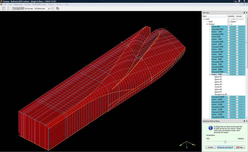
Preview on the IGES file.
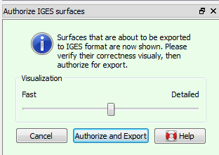
User authorization for export.
Export to CADMATIC (according to the SEUS convention)
This option does not provide any additional settings or selection options. It generates files that can be imported into CADMATIC, according to the standard defined and agreed upon within the SEUS project. This results in two files. One is an IGES file with the extension .2CADMATIC.igs, and the other is a CADMATIC configuration file with the extension .2CADMATIC.cfg. In addition, a text file containing comments intended for users is generated, with the extension .CADMATIC.remarks.txt. For conversion to CADMATIC, it is required that the entire hull shape is covered by larger quadrilateral regions. This can be done using so-called “IGES export patches” in the Fairway GUI, see [IGES export patch].
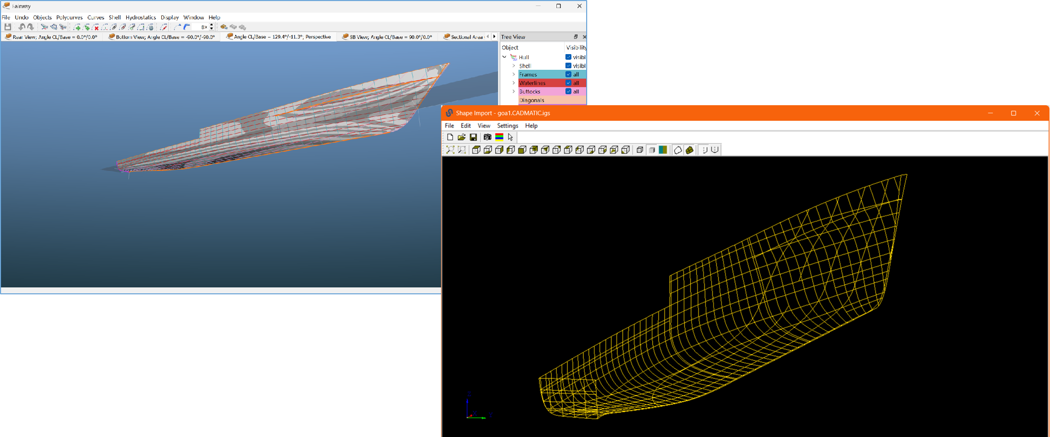
The Fairway model at the left transferred to CADMATIC at the right.
Export to STL or OBJ file format (for CFD or 3D printing)
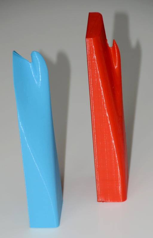
Model designed with Fairway, produced on an Ultimaker 3D printer.
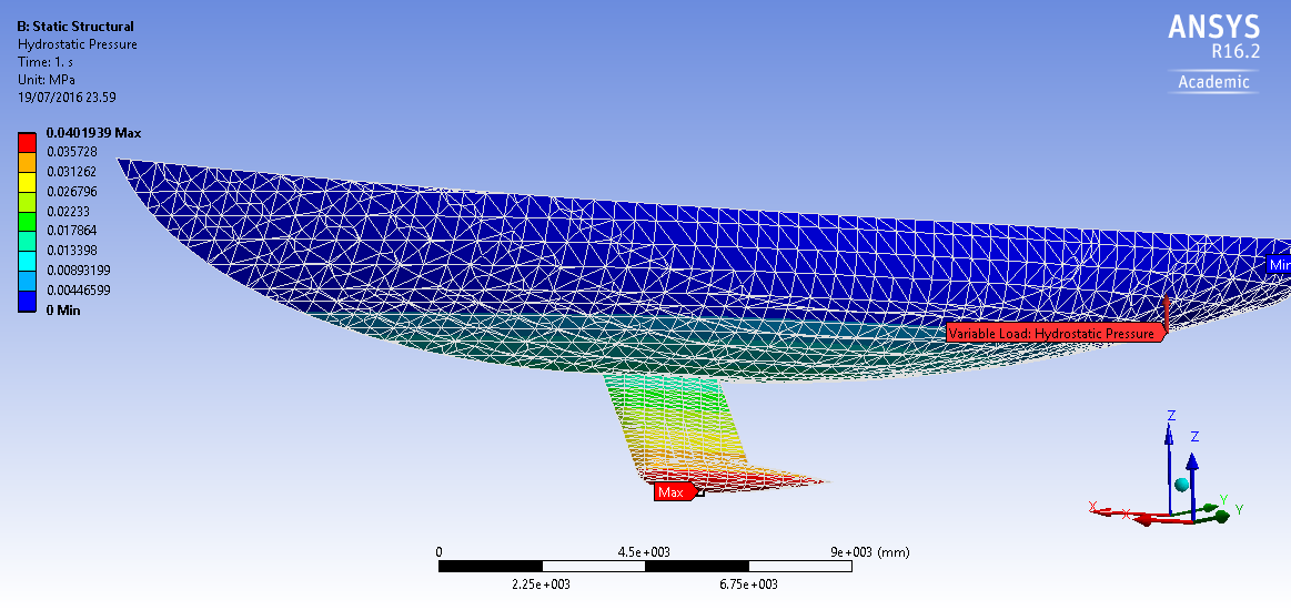
Fairway model, through STL imported in Ansys.
After selecting this STL/OBJ option, the program displays a menu in which the parameters discussed below can be entered. If this menu is exited in the normal way, the STL or OBJ file will be created. If this is not desired, the [Abort] function is available to leave the conversion menu immediately.
- Purpose
- The purpose for which the STL/OBJ file is produced, choice of ‘3D printing of a model’ and ‘CFD (Computational Fluid Dynamics)’. Differences between the two are:
- For CFD an even triangle distribution is sought as much as possible.
- For printing, the STL/OBJ file is in millimeters, for CFD in meters.
- For printing, a ship can be segmented (subdivided), for CFD that would be useless.
- Close at deck
- If the purpose is CFD, you can specify here whether the hull is to be closed at deck level (if this is not already the case). For 3D printing the shape is always closed, because a printer simply requires a closed solid.
- Format for output file(s)
- Choice between Wavefront OBJ and the two variants of STL
- Desired maximum triangle size
- Essentially, the STL/OBJ file format describes a long list of triangles. Here the desired maximum size of each triangle can be entered. It will be obvious that with a smaller triangle size the model will become more accurate, and the number of triangles (and thus the STL file size) will be larger. The triangle size specified here refers to the actual size vessel, and is therefore independant from the model scale. In the subdivsion proces from the surface into small triangles the ‘curved surfaces’ functionality of Fairway is applied, so it only works if that option has been purchased. Concerning the triangle size there are still a few differences between STL for 3D printing and for CFD:
- If a triangle is already fully flat, for 3D printing is not further subdivided, that would be useless. For CFD a different consideration applies, there it will be divided further.
- For CFD it may be useful to define areas of a coarser or finer triangle distributions. This can be assigned to a shell region, please see STL/OBJ export specifics. There it can also be set that a particular region is fully omitted from conversion to STL/OBJ.
- Model scale (reciprocal of
- Define the reciprocal of the model scale, so X in scale 1/X.
- Subdivide the ship
- Here the choice is offered between:
- ‘No, make full model’, which will also not subdivide. The export file will then simply contain the entire ship (i.e. the solids selected for export).
- ‘Yes, make demi model’, which will not subdivide the ship, but produce two separate halves, SB ans PS.
- Attention
- De specified triangle size is the maximum size, not the desired size. In other words, faces are being subdivided into smaller triangles, but not merged into larger ones. That would be impossible, because if two triangles are being merged, than usually a quadrangle is created, which does not fit into STL.
- All solids flagged for ‘export’ in the menu [Object management] will be converted to STL/OBJ. In this respect, one should be aware that the conversion is per individual solid, so the solids will not be merged together in the export file. If that would be desirable, external STL tools should be used for that purpose.
- Each phantom face (see Phantom face) is omitted from the conversion to STL. Furthermore, it is for the manufacturing of a demi model assumed that the ship is modelled in the conventional Fairway way. I.e. with a phantom face on CL.
- A solid of the type PS&SB a.k.a.  SB side of a symmetrical shape (so, extending over portside and starboard) is not automatically split in two when making a demi model. This must be done manually (with [Centerplane]→[Split] from the solid menu).
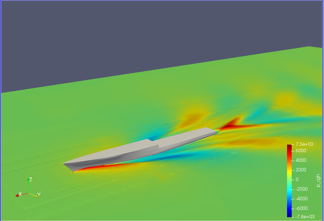
Fairway hullform exported to STL, imported in and computed with OpenFOAM.
Offsets to plain text file
With this option a text file (with extension .off) is generated, which contains the coordinates of all lines of the hull form. This file contains all solids which are selected for export, and has the following content:
- Name of the line.
- Number of points on the line.
- Longitudinal, transverse and vertical coordinates of every point (relative to to the intersection point of the aft perpendicular and the base line) in metres.
- Whether a point is a knuckle or not.
- Whether a point is an intersection or not. When the point is an intersection point, the intersecting line is given as well.
On production fairing
In this chapter the export facilities of Fairway have been discussed. The results can and will be applied in other (CAD and CAE) systems, often also for production purposes. In the latter case the Fairway hull form requires a level of consistency and accuracy which is sufficiently high for production. Fairway offers the user tools to fair for production. However, the actual fairness is dependent on the assessment by the user and the time that has been invested into the fairing process. The use of Fairway as a sole fact is by no means a guarantee that a hull shape is actually fair for production.