|
PIAS Manual
2026
Program for the Integral Approach of Shipdesign
|
|
PIAS Manual
2026
Program for the Integral Approach of Shipdesign
|
This action enables the user to quickly add planar polycurves to active solids by intersecting them with a plane, or a set of parallel planes. It is started from [Polycurves]→[New Planar Polycurve by Intersection] or with the keys <Alt><P><N>. These can then be used to manipulate the hull shape in higher detail and be exported to construction software. Polycurves also add visual detail, but if that is your only objective then you way want to see them just temporarily, which may be easiest with [Show Indicative Intersections]. Another way of adding polycurves is offered by the action [Connect Points].
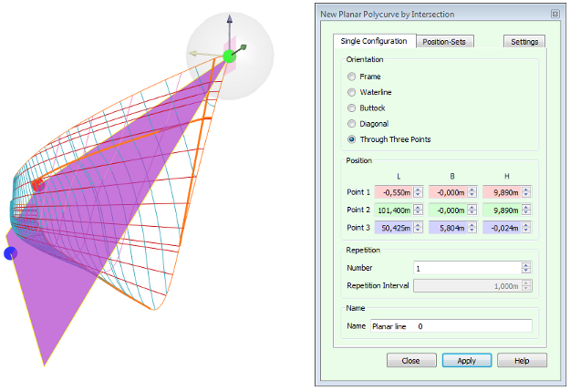
Planar polycurves can be added in two ways: either in manually configured positions and orientations or in stored configurations, the so-called position-sets. Each of these have their own tab in the action panel.
The [Single Configuration] is pretty straightforward, consisting of a choice of [Orientation] and accompanying [Position]. Most orientations are determined by just a single value, which in the case of frames may be given in the form of a construction frame number plus an optional offset in millimeters, if construction frames have been defined and are enabled (see Frame spacings). Planar polycurves in arbitrary orientations are defined in a plane through three points. The points are colour-coded in graphics and their corresponding input fields. The points can be moved by means of the dragger and by keying in values, and the plane through them is clipped to the maximum dimensions of the model. The planes in other orientations also have a dragger that they can be moved with.
There are two more groups on this tab and both of them are optional: [Repetition] and [Name]. With [Repetition] one can add several polycurves in parallel planes at once, by increasing the [Number] and specifying the [Repetition Interval]. The direction of repetition can be reverted by inverting the sign of the interval.
The [Name] field shows how the polycurve will be called when it is generated. You have the opportunity to change the name here, unless the repetition number is higher than one.
The [Position-Sets] tab shows a list of existing position sets (see Polycurve positions sets) with the option to check and uncheck them. Preview-planes will be shown for checked sets. The button [Edit Position-Sets...] allows you to add and remove sets from the list and change the positions in them.
The [Settings] tab in the upper right corner of the action panel automatically expands if the mouse pointer is moved over it. This tab contains settings with which the user can configure the accuracy in which new curves will match the existing curved surface. This is a model-wide setting, and is saved with the model.