|
PIAS Manual
2026
Program for the Integral Approach of Shipdesign
|
|
PIAS Manual
2026
Program for the Integral Approach of Shipdesign
|
*, but different extensions.
*.fwy | This is the main file that references the others. |
*.fw1 | Contains topological information consisting of points, edges and faces. |
*.fw2 | Contains general information about curves. |
*.fw3 | Contains geometric information in the form of NURBS vertices. |
*.fw4 | Contains special points. |
*.fw5 | Contains the name, main dimensions and coefficients, as well as the position sets and other settings. |
*.fw6 | Contains data for any defined linesplans. |
*.fw8 | Contains data for geometric dependencies between curves (master-slave). |
*.fw9 | Contains shell regions. |
*.cf | Contains groups of polycurves that are not part of a solid. |
*.sf | Contains connections between polycurves in the *.cf file. |
*.fw1, *.fw2, *.fw3, *.fw8 and *.fw9, as well as *.cf and *.sf depend on each other. Do not separate these when copying files.These file formats are intended to import curves — in the CXF, Curve eXchange Format — and surfaces — in the SXF, Solid eXcange Format — into Fairway. For backround and context reference is made to Import ship hull models in SXF/CXF format.
A CXF file is a plain ASCI file, with an even number of lines. Each pair of lines consists of a code (the first line) and an argument (the second line). The code defines the meaning of the argument. Behind the code a # may be placed, which precedes a comment. Lines that aren't immediately preceded by a code and start with a # are recognized as comment, and ignored. All units are in metres, the sequence of vectors is Length, Breadth, Height. SB = + and PS = -. Currently defined codes and arguments are:
   10     #File type (must be the letters 'CXF')
 CXF
   20     #File version (Must be 1)
    1
   30     #Creator (Description of program or person who created this file)
 Creator A
   40     #Project name
 Project ABCDEFG
   50     #Project version number
    N
   60     #Date (Year / Month / Day)
 yyyy   mm   dd
   70     #Time (Hour / Minute / Second)
   hh   mm   ss
 1000     #New solid (Currently only one solid is supported)
 Solid name
 1005     #Solid identification number (optional for single solid)
    N
 1500     #Solid attributes (internal to Fairway)
    N
 2000     #New line
 Line name
 2010     #Chine property (1=chine, 0=ordinary)
    N
 2020     #Plane type (0=frame 1=wl 2=buttock 3=diagonal 4=arbitrary plane 5=3D line)
    N
 2030     #Normal vector of plane (L, B and H components of normal vector)
    L.lllll     B.bbbbb     H.hhhhh
 2040     #Location of plane (metres from origin)
    P.ppppp
 2500     #Line attributes (internal to Fairway)
    N
 3000     #New segment
 Segment name
 3020     #Basic geometry type (1=polyline 2=NURBS)
    N
 3100     #Coordinates of polyline point (Length, Breadth and Height of a point)
    L.lllll     B.bbbbb     H.hhhhh
 3110     #Polyline point, specified as reference to a (unique) vertex number of the SXF file,
          #followed by the coordinates (Length, Breadth and Height) of this point.
    Vertex number       L.lllll     B.bbbbb     H.hhhhh
 3200     #NURBS Vertex (Length, Breadth, Height and Weight of a NURBS vertex)
    L.lllll     B.bbbbb     H.hhhhh     W.wwwww
 3300     #NURBS knot
    K.kkkkk
 3400     #NURBS order (order=degree+1)
    K
 3500     #Spline/segment attributes (internal to Fairway)
    N
 3505     #Spline identification number (internal to Fairway)
    N
 9999     #End of CXF file
    Optional CRC checksum, otherwise 0
Similar to the CXF file, an SXF file is a plain ASCI file, with an even number of lines. Each pair of lines consists of a code (the first line) and an argument (the second line). The code defines the meaning of the argument. Behind the code a # may be placed, which precedes a comment. Lines that aren't immediately preceded by a code and start with a # are recognized as comment, and ignored. Vertex locations are in metres, the sequence is Length, Breadth, Height. All faces must be oriented clockwise (seen from the outside). Currently defined codes and arguments are:
   10     #File type (must be the letters 'SXF')
SXF
   20     #File version (Must be 1)
    1
   30     #Creator (Description of program or person who created this file)
Creator A
   40     #Project name
Project ABCDEFG
   50     #Project version number
    N
   60     #Date (Year / Month / Day)
yyyy   mm   dd
   70     #Time (Hour / Minute / Second)
  hh   mm   ss
 1000     #New solid (Currently only one solid is supported)
    Solid name
 1005     #Solid identification number (optional for single solid)
    N
 1500     #Solid attributes (internal to Fairway)
    N
 2000     #Vertex number, plus coordinates of that vertex
    Vertexnumber    L.lllll     B.bbbbb     H.hhhhh
 2010     #Vertex number, plus name of that vertex
    Vertexnumber    name
 3000     #Edge number, plus the numbers of the two vertices bounding this edge
    Edgenumber       Number_of_vertex1    Number_of_vertex2
 4000     #Indicates start of face, face number
    Facenumber
 4010    #Edge of face: Reference to edge number & orientation (+1 or -1)
    Edgenumber      Orientation
 9999     #End of SXF file
    Optional CRC checksum, otherwise 0
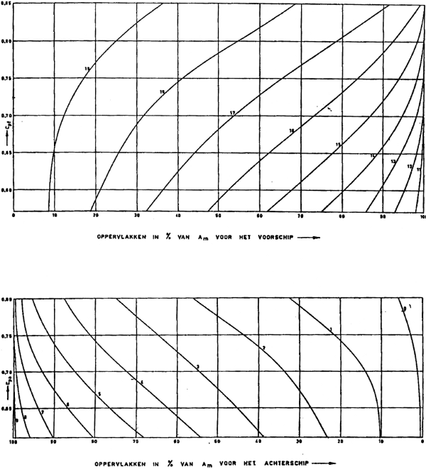
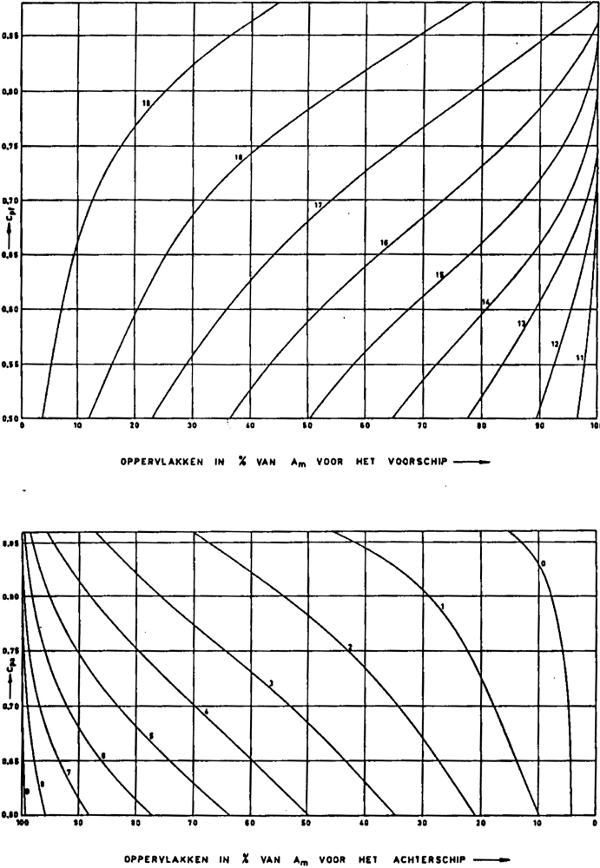
The file kvslap.txt in the PIAS installation directory contains the numerical representation of the diagrams of Lap, which are used to generate a target sectional area curve (target SAC) based on main dimensions, see [Change the shape of the SAC]. This is a text file, see ASCII text file. The diagrams give a frame area at various ordinates (longitudinal positions) through which the SAC can be fitted. The file format is explained here, followed by the represented diagrams. The information from this appendix allows you to adjust these diagrams.
The first half of the file is for single-propeller ships. After the row with the word DUBBELSCHROEF follows the information for twin-propeller ships. Each of these parts consists of a diagram for the aft ship and a diagram for the fore ship.
Each diagram starts with a row with two numbers. The first number is the number of prismatic coefficients in the table, the second is the number of ordinates in the table. Next follow the prismatic coefficients, each on a separate row. Finally follows the table of percent values of the midship area, each ordinate on a row of its own. The first column gives the ordinate number, followed by a column for each prismatic coefficient.
As an example you will find the representation of the diagram for the fore ship of single-propeller hulls below.
8       11
0.55
0.60
0.65
0.70
0.75
0.80
0.85
0.9
10      100     100     100     100     100     100     100     100
11      96.9    98.7    99.6    100     100     100     100     100
12      91.2    95.1    98.1    99.8    100     100     100     100
13      82.8    89.6    94.2    98.1    99.8    100     100     100
14      70.5    80.4    88.5    94.5    98.1    99.9    100     100
15      57.1    67.4    77.4    86.8    93.7    98.4    100     100
16      43.9    52.2    62.1    72.8    83.4    92.5    98.9    100
17      29.1    36.4    43.9    53.6    65.2    78.5    91.5    99.1
18      16.9    21.1    25.4    31.4    41.1    54.7    68.7    79.6
19      8.2     8.7     9.7     12.1    17.2    25.2    36.1    45.2
20      0       0       0       0       0       0       0       0
Changes in the user preferences of the GUI, [File]→[Preferences...], are saved in a text file in a directory defined by the operating system. By copying this file it is possible to manually manage several variations of user preferences, including the transfer to other installations. For example: for a demonstration on a projector or while recording a screencast it can be beneficial to temporarily work with thicker lines and colors of higher contrast; and for illustrations on paper a white background and darker curves work better (see also Adjusting hotspot appearance). Configurations for these occasions are easily saved and restored by hand.
The file containing the customized preferences (as far as they divert from the default) carries the name Fairway.ini and resides in a directory called SARC. The location of that directory depends on the Windows version and is typically configured in the %APPDATA% environment variable. Examples are C:\Users\User Name\AppData\Roaming\SARC\Fairway.ini and C:\Documents and Settings\User Name\Application Data\SARC\Fairway.ini.
The appearance of the draggers, with which the position of points and other elements can be manipulated, can be adapted to personal preferences. This is done by editing one or more geometry files.
The default geometry of the draggers is compiled into the program, but an image thereof is contained in the *.iv files in the installation directory. These are not used by the program as it is, but it is recommended to leave them untouched, for reference of the default geometry.
arrowedTranslate1Dragger.iv contains the geometry for the linear dragger.arrowedTranslate2Dragger.iv contains the geometry for the planar dragger.arrowedTranslate3Dragger.iv contains the geometry for the spatial dragger.You should know that the linear dragger is used twice inside the planar dragger, and the planar dragger is used three times inside the spatial dragger. So, in order to maintain uniformity, if one of these files is changed then a similar change may be needed in the other files.
To use custom versions of these files, perform the following steps.
*.iv files from the installation directory to a directory of your choice. Do not rename the files.notepad.exe (see ASCII text file).SO_DRAGGER_DIR to point to the directory with the modified files.After a short introduction to the file format, we will give a few examples to experiment with.
The format of the geometry files follow the Open Inventor File Format. You don't need to know this format in detail in order to make simple changes, the contents of the files are quite comprehensible. But if the format is violated then the file will fail to load and the dragger will have no geometry at all. If you cannot get it to work, just delete the file completely and the system will fall back to its compiled-in version.
We follow the convention that identifiers in all-capital letters are only used within the file in question. Mixed case identifiers are referenced by the program to construct the final geometry of the draggers.
If you want to know more about the format, here are some pointers:
The on-screen size of the draggers is held approximately constant, irrespective of the camera zoom level and distance. This is accomplished by the use of a SoConstantSize node and its value field projectedSize. Let's say that arrowedTranslate1Dragger.iv contains the line
DEF ARROWED_TRANSLATE1_CONSTANT_SIZE SoConstantSize { projectedSize 50 }
This defines the identifier ARROWED_TRANSLATE1_CONSTANT_SIZE. Whenever this identifier is used in the file, 1 unit size in the geometry following after it (within the same Separator) will approximately be 50 pixels on screen.
So, in order to increase the size of the dragger, it suffices to change the above line into
DEF ARROWED_TRANSLATE1_CONSTANT_SIZE SoConstantSize { projectedSize 60 }
You will want to repeat this exercise in arrowedTranslate2Dragger.iv and arrowedTranslate3Dragger.iv.
Dragger axes are represented by arrows. The arrow head is constructed by means of a Cone node, with fields for height (arrow head length) and bottomRadius (arrow head width). You could make the arrow more articulate by increasing bottomRadius, for example.
Again, you will want to repeat this exercise in arrowedTranslate2Dragger.iv and arrowedTranslate3Dragger.iv.
The “hotspot” of a dragger is the transparent sphere around the arrows that reacts to mouse clicks, which eases picking of the dragger. Depending on your monitor, you may find that the rendering is too weak or too strong. This can be corrected by adjusting the transparency field in the ARROWED_TRANSLATE?_HOTSPOT_MATERIAL nodes in arrowedTranslate1Dragger.iv and arrowedTranslate2Dragger.iv. If you prefer to not see the hotspot at all, you can set transparency to 1.
If you have configured a white modelling view background, instead of the default, you way want to increase the contrast by setting the red, green and blue values of the colour fields of the hotspot material to
    diffuseColor 1.0 1.0 1.0
    emissiveColor 0.0 0.0 0.0
    specularColor 1.0 1.0 1.0
    transparency 0.85
    shininess 1.0
When translating in a plane, the plane is rendered transparently in the corresponding color. If you do not like this, the plane can simply be disabled by editing arrowedTranslate2Dragger.iv as follows. Comment-out all lines between the opening and closing curly-braces of the identifiers arrowedTranslate2FeedbackOrthogonalActive and arrowedTranslate2FeedbackArbitraryActive, by putting a “#” in front of each of these lines.