In
PIAS renewals (2012-2014) the renewal of PIAS is discussed. One aspect of that process is that the
Compart module is being replaced by the much more powerful
Layout module. Because the
Layout technology can only be incorporated in the rest of PIAS gradually, a number of subsequent module which uutilize compartment information, such as grain heeling moments and damage stability, will for the time being maintain to use the
Compart data format. For this reason one might be using
Compart occassionaly, and therefore its manually is still included in this manual. Please be advised that:
- This manual is simply the old, existing Word version, copied here, without further editing or modernization. So this chapter is not exemplarity for the current PIAS manual.
- The use of Compart for modelling or computations is disencouraged. Layout is recommended instead.
- Compartments which are converted from Layout can be viewed in Compart, however, they can not be editted. In order to avoid possible inconsistencies, see Compartment files for further discussion.
Main menu
Define/edit compartments
This option enables you to define the compartments. After selecting this option choose `New' from the menu to add a new compartment. First you have to enter a name of the new compartment. Every name has to be unique, whith a maximum length of 28 characters. Actions, such as the calculation of capacity tables are performed on selected compartments. Compartments can be (de-)selected by selecting the first column. All compartments can be de/selected simultaneously with `Deselect' / `Select'. You can combine compartments with [mErge]. This option can be very useful when calculating, for example, the damaged stability of the engine room. Then you need not define a new engine room without tanks by hand, but take the whole engine room compartment and subtract the tanks. First select all tanks in the engine room, make a new compartment and choose `mErge'. Set this compartment on `negative' (in the sub-compartment definition). Select the new compartment and engine room, make a new compartment and choose `mErge' again. With option `Graphical' you will get an overview of all defined compartments. The compartment which is selected in the list of compartments will be printed in white, all other compartments have a random colour. If you move the cursor in the selected window, the name of the compartment on the position of the cursor is printed in the lower left corner. If the option `Overlap on/off' of the toolbar is selected, all compartments will be printed in green and a possibly singular overlap of two compartment in red.
Define/edit general particulars of this compartment
The following input menu appears:
- Weight group: Here a weight group number can be entered. Weight groups can be defined in module Loading, and are used to keep compartments with the same content (such as fuel oil, of potable water) together at the output of loading conditions.
- Density: This is the density, the specific weight, of the contents of the tank (ton/m3). With `V' the density is defined to be variable, which means that for any tank reading or calculation of tank capacity the program asks the user for the density. This mechnism can be used if the specific weight is not fixed for a particular tank.
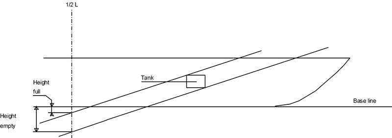
- Sounding pipe data: The parameters for a sounding pipe are only displayed if no curved sounding pipe has been defined. The sounding pipe defined here will be a straight vertical pipe at a longitudinal distance from the App and a vertical distance from the baseline. See the figure on the next page. A curved sounding pipe is defined at option 1.3. - Define position pressure gauge Here the location of the pressure gauge is defined in length, breadth and height. These particulars are used for the output of tank capacity tables including pressure (see the configuration of the output-script at option 3.9). - Space type (for prob. damage stab.): WIthj the calculation of probabilistic damage stability according to SOLAS 2009, the permeability can be dependant on the destination of a particular compartment. This `space type' can be defined here. There is a distinction between predefined and user-defined space types, see the Probdam module for more details.
- Tank type (for outflow calculations): For probabilistic oil outflow calculations (see module Outflow) it is a prerequisite that the type of compartment is explicitly defined. In this context `fuel oil', `cargo oil' and `non-oil' are distinguished.
- Overpressure of inert gas system: Cargo oil tanks can be equipped with inert gas systems. Inthat case it is relevant for the oil outflow calculations to specify its overpressure, in kiloPascal.
- Tank is bounded from below: For the same outflow calculations it can be relevant whether a tank is bounded from below by the bottom, or by a non-oil compartment. This can be entered here.
- Identical permeability tank volumes / damage stability for all sub-compartments: With this option all sub-compart-ments which belong to this compartment will receive the specified permeability. For the permeabilities also see option 1.2.1.
- All subcompartiments to side: This option will only be displayed if all sub-compartments of this compartment are defined at one side or both sides of the vessel. If you change the side here all sub-compartments of this compartment will be defined at that side. This can be useful if two identical compartments have to be defined with one on SB and one on PS. One menu back you can copy one compartment to another by choosing `Copy'/`Paste'. The copied compartment can then be transferred to the other side of the vessel with this option.
Define/edit sub-compartments
Every compartment is defined by at least one sub-compartment. Complex compartments can be defined by a lot of sub-compartments. If appropriate the compartment will automatically be limited by the hullform. The name of a sub-compartment must be unique, its maximum length is 28 characters. By the `enter' key, or by double-clicking the mouse, the sub-comparment definition menu appears:
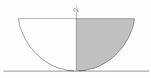
- Side: Transverse coordinates are always positive. If a compartment extends from PS to SB, define only the SB side (the gray area in the figure below) and choose `Double (PS&SB)' for `Side'.
- Warning
- Asymmetrical hullforms cannot contain double compartments. The port side and starboard side have to be defined separately in case of an asymmetrical vessel.
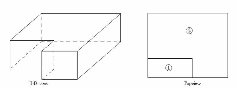
- Sign: For further explanation see the next figure. The actual compartment (3-D view) consists of two sub-compartments (top view) where part 1 is negative and part 2 is positive.
- Permeability: Two values can be specified: the first permeability is for determining tank capacities, the second for damage stability calculations. The calculation of actual grain moments (Grainmom) is performed using the `permeabil-ity for tank sounding tables'. The permeability is defined as the total volume excluding the volume of the con-struction parts divided by the total volume including the volume of the construction parts and has a value between 0 and 1.
- Autopermeability probabilistic damage stability: If this option is set to `yes', the permeability will automatically be determined according to the appropriate regulations of probabilistic (and deterministic, in case of IMO A.265) stability calculations, these days that is only Probdam.
The sub-compartment can either be defined by bulkheads or externally.
- Bulkheads: This sub-compartment is defined by a vertical fore and aft bulkhead. The sides of the sub-compartment can be slanting. The hullform can also be the limitation of the sub-compartment.
- External (only available if separately purchased). Complex compartments or, for example, cylinders can be defined externally as if they were a ship. The module PIAS for hullform definition, Hulldef, can be used for this purpose.
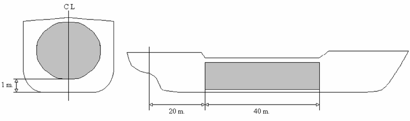
This external compartment is defined as follows: with the module from chapter 70the aft bulkhead is placed at distance 0 m. the forward bulkhead at 40. This "ship" is saved as CYL. In the menu for definition of an external compartment we enter:
- Filename external compartment: cyl.
- Longit. distance origin ship-extern = 20 m.
- Transverse distance origin ship-extern = 0 m.
- Vertical distance origin ship-extern = 1 m.
Constraints for external sub-compartments:
- An external compartment can only be declared `double' if the transverse distance is 0.
- Always check the compartment with a three-dimensional view of the compartment at option 1.6.
- An external sub-compartment will not be limited by the hullform (so it can extend beyond the vessel's side).
- Longitudinal distances of bulkheads from App: The bulkheads are always perpendicular to the centreplane and the horizontal plane. If a compartment is limited by the hullform the aft or/and fore bulkhead can be placed at a longitudinal distance which is larger than the length of the vessel. This way f.e. the forepeak will be defined exactly by the hullform.
- Boundaries: The side boundaries of a compartment are defined by the four vertices of the aft and fore bulkhead. This means the boundaries of a sub-compartment are always straight lines. The four vertices are (see also the sketch below):
- Inside under
- Inside upper
- Outside under
- Outside upper
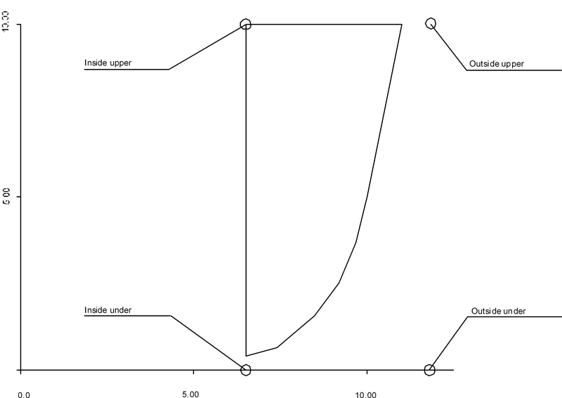
Some values are already defined with a `>>' or ∞ symbol. This means the co-ordinate is far outside the hullform, therefore the boundary will be the hullform (deck or side). Values greater than 100 are displayed with a these symbols. A limitation in the definition of the sub-compartments is that the cross section must be convex, which means that none of the internal angles may be greater than 180°. Always make a visual check of each sub-compartments. It is also possible to specify boundaries of sub-compartments relative from a reference plane. To choose a reference plane choose rEference, after which a menu of defined reference planes appears. When reference to a plane is made, all co-ordinates are relative with respect to that plane. Finally, in this definition menu a number of functions are active (`Plot', `3D screen' en `3D paper') which can be employed to draw section in front view or threedimensional on screen or on paper.
Define/edit curved sounding pipe
An input screen appears to define the co-ordinates of the sounding pipe. The number of co-ordinates of the sounding pipe should be between 2 and 15. The sounding pipe is defined by straight lines through the co-ordinates. The pipe must be defined upwards. The sounding pipe can be checked in a three-dimensional view with options 1.5 and 1.6. If a curved sounding pipe has been defined, option 1.1. will not display any sounding pipe data.
- Longitudinal location, the longitudinal distance from App.
- Transverse location, transverse distance from centreline where SB is positive.
- Vertical location, vertical distance from baseline.
Define location alarm sensors
In this menu a maximum of three alarm sensors may be specified, by giving their name and location. When a sensor is defined, a printed tank sounding table is preceded by the relevant values at a liquid level which just touches the sensor.
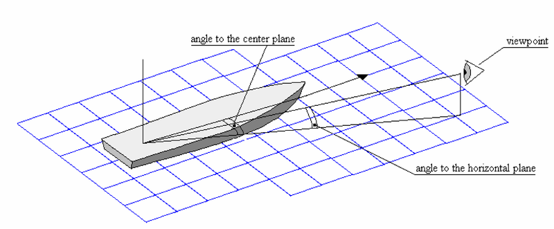
Three-dimensional plot of this compartment
All sub-compartments and the curved sounding pipe, if defined, are plotted on the screen or paper. The angles to give are the viewing angles, as depicted in the figure below.
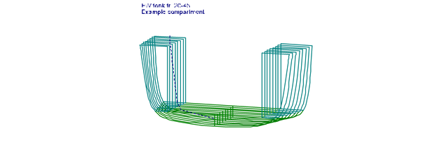
External sub-compartment will be plotted as well. An example is depicted below (with the dashed line being the curved sounding pipe).
Print or plot inputdata compartments on screen or paper
The following menu appears on the screen:
Print input data of selected compartments on paper
The input data of all selected compartments (selected in option 1) are printed on paper.
Three-dimensional plot of selected compartments on paper
A three-dimensional plot of all selected compartments will be printed on paper.
Plot cross sections of selected compartment on paper
All cross sections of the selected compartments are printed on paper.
Compare internal and external geometry
With this option a graph is drawn, where on many cross sections the difference between sectional area (derived from hullform) and sum of the compartment areas (derived from compartment definition) is displayed.
This difference, which should be zero theoretically, may indicate the presence of lacking or double compartment definition. For probabilistic damage stability calculations this check is recommended. Besides, small differences may occur due to properties of the numerical methods used.
Plot tank plan on screen or on paper
Define views/sections
Please refer to Sketches of tanks, compartments and damage cases.
Selected views/sections on screen/paper
This will print the view or sections as defined at the previous menu option. At each drawn compartment an identification is printed. Depending on the setting of the switch `Tank sketches with automatic tank numbers' (see Settings for compartments and tank sounding tables) as identification either anumber, determined automatically by the program, is used, or the first four letters of the second name.
Calculate and print tank sounding tables
In order to calculate tank sounding tables, you first have to define trim and vertical increment at option 3.1. Computing time depends on the number of trims, vertical increment and the complexity of the hullform. With option 3.3 the tank sounding tables can be displayed on the screen and edited, if desired. After calculating the output script can be defined in option 3.9. This means you can specify what must be printed in the tank sounding table, such as height, volume, pressure etc. All features are explained below:
Define/edit trim and vertical increment
Edit trim for the tank sounding calculations
An input screen appears at which you can enter one or more trims to calculate the tank sounding tables.
Edit vertical increment for the tan ksounding calculations
The current vertical increment is displayed. You can enter a new value or press `Enter' to keep the current value. This vertical increment is also used to print the tank sounding table on paper. For accurate values the vertical increment should not be too large. You can toggle a switch to calculate extra lines at the end of each tank sounding table, at option `Setup for compartments and tank sounding tables' (see Settings for compartments and tank sounding tables).
Define 1 trim for the tank sounding table to print
If the tank soundings are calculated for more than one trim, whereas you want only one trim to be printed, this trim can be defined here. This trim will not be saved, so every time you print a tank sounding table you have to define the trim if you want to use this option.
Calculate tank sounding tables of selected compartments
All selected compartments are calculated for the defined trims and using the defined vertical increment. The results are stored as tables in a file. The result can be displayed and edited with option 3.3.
View/edit calculated compartments
All calculated tank sounding tables can be displayed and edited if you wish. After selecting this option, all compartments appear on the screen. Select the desired compartment for displaying the sounding table. An input screen appears with the calculated values of this compartment. The calculated values can be changed. No lines can be added. When a tank is used in a loading condition, this table is read. Intermediate values are calculated by linear interpolation. So accuracy improves when the vertical increment decreases.
Print selected sounding tables according to output script on paper
All calculated and selected compartments are printed on paper according to the defined output script (option 3.9).
Print tables of litres of selected compartments on paper
Will print a liter table. The tank should have been calculated with a small vertical increment.
Print trim tables of selected compartments on paper
Trim tables can be printed on the basis of sounding or pressure.
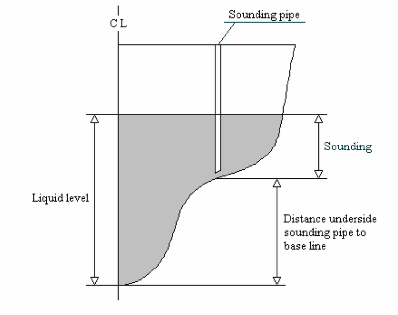
- Based on sounding: Tables are printed where at each line sounding (in meters) and volume at each calculated trim is printed. If a sounding pipe is defined with option 1.3, ullage can also be printed.
- Based on ullage: If a sounding pipe is defined with option 1.3, tables are printed where at each line ullage (in meters) and volume at each calculated trim is printed. The soundings can also be printed.
- Based on pressure: Tables are printed where at each line pressure (in mm water pressure) and volume at each calculated trim is printed.
View date of tables or remove calculated tables
This option displays the date of definition of the compartments and the date of calculation of the tank sounding tables. This way you are able to check if the compartment has been changed after the table was calculated. To remove a tank sounding table, select the compartment.
Print summary of maximum tank volumes on paper
This option enables you to create a list with per compartment one row with the maximum volume, the centres of gravity, the maximum free surface moment transverse and the density (if defined). Notice that the maximum volume and the maximum free surface moment are not necessarily at the same height. The maximum value of both variables is determined separately from each other.
Change output script
This option enables you to define which variables have to be printed in which order and in which unit. An input screen appears with the variables in the left column and the unit in the right column. The first row will be the first column on paper.
- To print the ullage, a curved sounding pipe has to be defined.
- To print the pressure, the pressure gauge has to be defined at option 1.4. The pressure is calculated perpendicular to the waterline (not in ship's coordinate system).
The height of a tank sounding table is the height of the level of the liquid related to the PIAS reference points as defined in Definitions and units. When a tank sounding table is calculated with a trim not being zero, large or small (negative) values for the height are possible. The height is defined at half the length above baseline. The start height is at tank volume zero, the end height is at maximum tank volume.
Calculate and print tank sounding/ullage correction tables
With this option the correction tables can be made to calculate the tank volume when the ship is trimmed. The trim and height step are used as given in option 3.1. Secondly, the list as given in the general settings (Config) is used. The correction is made as follows:
- Look up the tables of the intended tank (there are two tables for each tank).
- Look up the first correction in the trim-table at the correct sounding/ullage and trim.
- Look up the second correction in the list table at the correct sounding/ullage and list.
- Add the first and second correction to the sounding/ullage. This is the sounding/ullage that can be used to read out the tank volume at trim and list zero.
Define reference planes
Without special instructions the boundaries of sub-compartments are specified as absolute distances in the standard co-ordinate system (= distances from APP, CL and baseline). It is also possible, however, to specify boundaries of sub-compartments relative from so-called "reference planes". The advantage of that definition is that shifting a reference plane causes all connected boundaries to shift also. In the design stage this mechanism can be very useful, in the forward part of the vessel, for instance, all transverse boundaries may be specified relative from a reference plane coinciding the collision bulkhead. When the collision bulkhead is moved, adapting the location of the reference plane only leads to the correct modification of all connected tanks. This mechanism, which we call `relational', may sometimes be called `topological' or `associative'. The reference planes which are defined in one of the three orthogonal directions (transverse, longitudinal and horizontal) can themselves also be defined relative to another reference plane. An oblique reference plane can be defined with the absolute coordinates of three points which lie in that plane. When defining a reference plane, the following properties can be specified:
- Code. This is a short name of maximum 6 characters, which is used as a short identification of the plane in menus which too ample space for longer names.
- Location. This is the shortest distance between the plane and the origin. At planes in one of the three orthogonal directions this is the position of the plane, which can simply be typed. in. At oblique planes the orientation is fixed by three points which coincide with the plane. If one should try to type in the location of an oblique plane, a menu appears where the coordinates of those three points can be given.
- Name. The full name of the reference plane.
- Bounded. Initially a plane is infinite, so unbounded. However, with this option the boundaries of a plane can be specified, so the plane not only serves the role of reference plane, but can also be seen as a construction part. PIAS' calculation modules do not utilize this boundary information, but lay-out modules might use it. In the plane-boundary menu the user is supposed to define a path which serves as boundary. The `Generate' function is an aid which generates that path on basis of 4 parameters.
- Side. Here it can be specified whther the reference plane is situated on SB, PS or both sides.
In each menu where reference planes are used, the following facilities are available:
- With the `rEference' function it can be selected to which plane the plane under consideration will refer. With the regular function keys the distance from that reference plane can be specified.
- With the `Enter' key the full name of the plane to which the coordinate under consideration refers is shown.
- While typing in coordinates, the code of a reference plane can simply be co-typed. Suppose one should wish to define a point at 2 m from plane `abcdef', then typing in `abcdef+2' wil suffice.
Basic version
If only the basic version has been purchased the following limitations apply:
- A maximum of 70 sub-compartments.
- No tank arrangement plan available, option 2.5
- No three-dimensional plots of compartments
- No external compartments
- No Imperial units, option 3.9
- No tank sounding tables in liters, option 3.5
- No trim tables, option 3.6