instead of being related to a specific PIAS module, this chapter describes a number of tools which can be applied at multiple tasks, and which are consequently included in a number of modules, which are:
Weight groups
A weight group is a category of cargo or other loading, for example `ballast water' or `heavy fuel oil', and is introduced to provide some order is lists of compartments and weight items. If weight groups are being used then, where relevant,
Loading will also generate subtotals (of weights and sometimes also COGs) per weight group. Please realize that the concept `weight group' is an auxiliary tool,
its use is not obligatory.
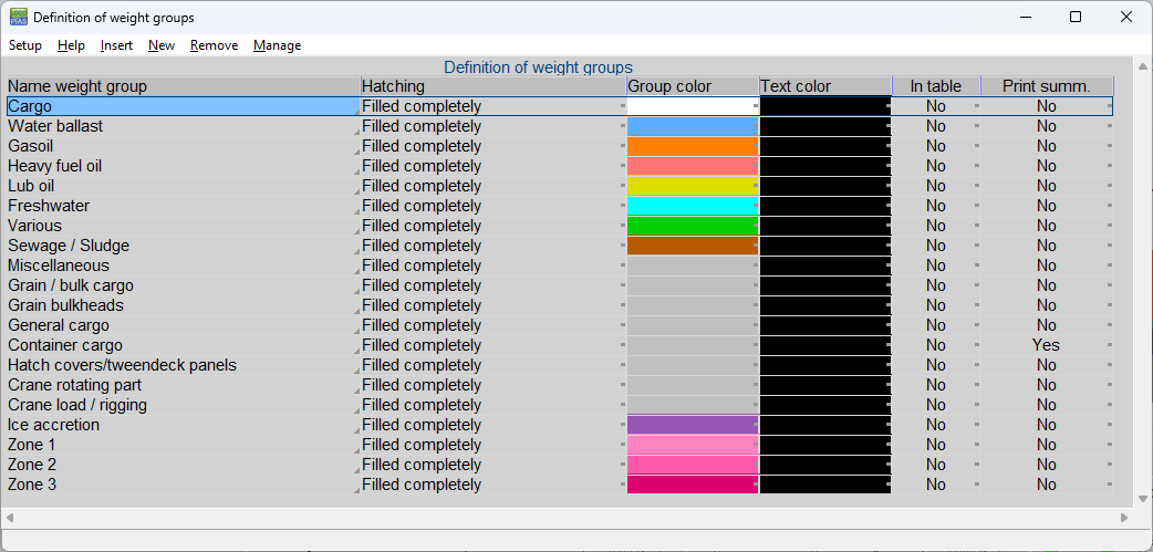
Weight groups can, up to a maximum of forty, be defined from Loading and Layout, an example of the input window is shown below. Each compartment or weight item can be assigned to a particular weight group by pressing <Spatie> there, which pops up a selection window with all full weight group names. It is also possible to create a new weight group here.
For each weight group can be given:
- The name, just a description.
- The hatching type which is used when hatching or filling in the compartments in tank sketch plots, as discussed in Sketches of tanks, compartments and damage cases.
- The group color, which is the color representing this weight group, and which is used in plots, and also as background color in text windows if the last column of this weight group is set to ‘yes’.
- The text color, which, if the last column is set to ‘yes’, specifies the foreground color in textual overview windows of the texts which belong to this weight group.
- In table, which indicates whether the weight group color should also be used in overview tables of compartments and weight items.
- Print summ., which indicates whether in the output only the subtotal should be printed. The calculation is based on all weight items though.
Additionally, a specific function apply:
- With [Move] a weight group can be moved in the list.
Specify weight group properties
Sketches of tanks, compartments and damage cases
If this option has been purchased, it enables you to define views and section which will be used when printing compartment definition data, with damage stability calculations and with loading condition to generate large-scale (= small-size) drawings of compartments and hullform etc. The color and hatching type of these graphics can be specified per weight group, for which we refer to
Weight groups. If multiple sketches are defined they will be ‘pasted on paper’ beneath each other, an example of the output is present at the end of this chapter.
This menu, where the sketch parameters can be given, can be called from many loactions, such as from Loading or Layout, but also from the general configurations with Config or equivalent. In each of these cases an input window appears where on each line the properties of one sketch can be given, with per column:
- The first three columns, compart, intact and damage, determine whether this sketch is added to the output of compartment definition output from Layout, intact stability calculations and damage stability calculations respectively. In the output of intact stability calculations each compartment which is filled to some extent will be fully hatched, so no distinction will be made between partially and fully filled tanks.
- The fourth column defined the type of sketch, where the choices are:
- Vertical section.
- Horizontal section.
- Cross section.
- Side view.
- Top view.
- List of compartments. This is an alphanumerical list of compartments which are relevant in this sketch.
- Wind contour, which is only used in the output of intact stability.
- Probability triangle, which is only used in the output of probabilistisc damage stability.
- Hopper cross sections, applicable only if there is a hopper and in the output of intact stability.
- Hopper vertical section, applicable only if there is a hopper and in the output of intact stability.
- Location, the location of the sketch, if applicable.
- Damage center, ensures that the sketch is always taken through the center of the damage case. Applies only to sketches selected for damage.
- A reduction factor on the plot size. A factor of X will reduce the size of the sketch by X.
- Axis & scale, which is used to specify whether a horizontal axis and a scale must be co-plotted.
- Horizontal axis, here can select the unity for the horizontal axis; meters or frames.
- Identification compartment, here you can choose how a compartment is indentified in a picture. The choice is between:
- An automatically generated number
- The name of the compartment
- The second name of the compartment
- The abbreviation
- No identification If a legend is printed, at least a number is printed with the tank, possibly supplemented by name or abbreviation.
- Waterline, a setting that indicated whether the waterline should be drawn as well into the sketches of the intact stability and the deterministic damage stability.
- Filling, if in the compartments the filling level is to be hatched, only valid for intact stability.
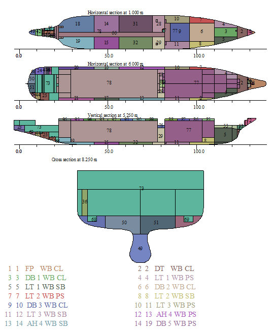
A page with tank sketches containing 4 sections and a compartiment list
Input and edit damage cases
This tool, designed to define and edit damage cases, can be called upon from all modules which perform a damage stability task, both deterministic and probabilistic. Basically, this tool is rather simple, after all compartments have already been defined (with
Layout), and here they can be clicked to toggle them between ‘flooded’ and ‘not flooded’. This tool contains a text window at the left and three graphical windows with three sections, see the example below.
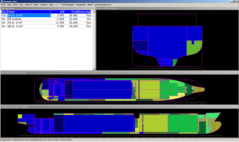
Damage cases
In the graphical windows the damaged compartments are indicated with a blueish color, non-damaged compartments in green-yellow. With the mouse the cursor can be placed or moved in such a window, which will make that the other sections will be adapted to the mouse position.
- Attention
- Before December 2021, the Loading, Hydrotables (maximum allowable VCG in damaged condition) and Probdam modules had their own list of damage cases and there was an Import option to transfer damage cases from one list to another. From the above mentioned date all damage cases are in 1 list and each damage case can be switched on or off for each type of calculation of a module. All existing damage cases are merged into this list. By default, only those damage cases that are selected for the module in question are visible, but with the option ‘View’ the whole list can be made visible.
The columns in the text window have the following meaning:
- Slct, selected, yes or no.
- Lock, a damage case can be locked for changes.
- Name, the name of the damage case.
- Aft and Fore, being the aft and forward boundary of the damage. These parameters are relevant for the damage stabilitycriterion ‘deckline not submerged outside flooded area’, and for a calculation according to STAB90+50, because there the freeboard is taken into account. Recall that the freeboard is calculated from the deckline, the way of defining which is addressed at Deck line. If these criteria do not apply, the boundaries need not be specified.
- Upper, Ainside and Finside, upper, aft inner and forward inner boundaries of a generated damage case in the probabilistic damage stability.
- Crit.final and Crit.interm., one can select an alternative set of stability requirements for this damage case.
- Level interm., one can set a different setting for the water level during an intermediate stage of flooding.
- Flood.stages, here it is indicated whether a complex intermediate stage — a concept for which reference is made to Complex stages of flooding (before 2023) — has been defined for this damage case.
- Higher subd., here it is indicated whether for this damage case higher subdamages should be calculated. The higher subdamage exists as interpretation of a lesser extent of damage as described in SOLAS part B-1 regulation 7.6: “The assumed vertical extent of damage is to extend from the baseline upwards to any watertight horizontal subdivision above the waterline or higher. However, if a lesser extent of damage will give a more severe result, such extent is to be assumed”. With this option switched on, additional damage stability calculations will be made with tanks or compartments below a systematic set of horizontal boundaries non-flooded.
- Valid Loading/Hydrot./Probdam, here is indicated for which kind of calculation the damage case should be included, provided that the damage case is also selected.
Additionally, a number of specific functions apply:
- With [Flooding stages] non-standard intermediate stages of flooding can be defined, this is futher discussed at Complex stages of flooding (before 2023).
- With [damage Box], interactively a rectangle can be dragged, which makes the contained compartments flooded. This is a quick and consistent tool for declaring a large number of compartments flooded simultaneously.
- With [Edit damage boxes] multiple damage boxes can be created that can be quickly switched between using the ‘Selected’ column. The other columns will speak for themselves.
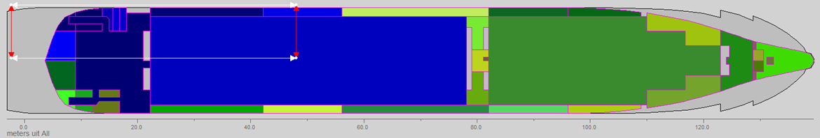
- When the option [start selected damage Box] is activated, in the three graphical windows three white rectangles pop up, which are the projections of a three-dimensional rectangular damage. The vertices of the rectangles can be dragged, which adjusts the damage size and location. If the mouse button is released the flooded compartments are colored blueish, see the example below. By pressing the right mouse button on the rectangular damage the size and location can also be modified numerically. The ‘Fixed’ apsects of a damage box are graphically visible by colouring the lines and arrows red if necessary. Note that selecting another damage case ensures that adjustments to the previous damage case are no longer undoable.
- With [Create new damage case with selected compartments] the current damage case is added to the list of damage cases and a new damage case is created which can then be modified.
- With [quit damage box]→[ do Not save damaged compartments] stops the damage box and changes to the damage case are not kept.
- With [quit damage box]→[ Save damaged compartments] stops the damage box and the changes made to the damage case are saved.
- With [iMport], damage cases can be read from an XML file (if purchased).
- With [Unit longitudinl axis] the unit of the longitudinal axis can be chosen, where the choice is between meters and frames.
- With [Output] the selected damage cases can be printed and plotted, suboptions:
- [Print input data of selected damage cases] : Produces a list, which contains for each selected damage case the names of the belonging damaged compartments.
- [Definition of sections for sketches of damage cases] : Use and background of this option is discussed in Sketches of tanks, compartments and damage cases.
- [pLot of selected damage cases] : With this option sketches of the selected damage cases will be printed according to the specification as given in the previous option.
- [pRint permeabilities of all compartments] : This option only appears in case of the probabilistic damage stability. With this option a list of permeabilities assigned to the distinct types of spaces is being printed.
- [plot of Zonal boundaries] : This option only appears in case of the probabilistic damage stability with the zonal method. It will generate a single plot, which contains the compartments and the zonal boundaries, at the sectionsas specified with Sketches of tanks, compartments and damage cases. See the example below.
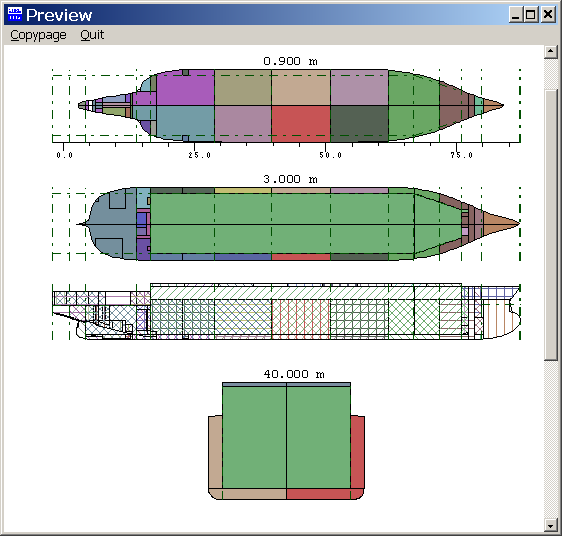
Preview zonal boundaries
Interactive damage box
Finally, with the <Enter> key a subwindow opens up, as depicted in the figure below, where form each compartment is stated whether it is flooded. The last two columns, containing the intact weight and the intact density, only appear when defining damages for maximum allowable VCG in damaged condition, for at those computation these intact content plays a role because it will flow out in case of damage (at the deterministic damage stability of a particular loading condition, as can be computed with Loading, the intact content obviously also flows out, but need not to be defined separately, becaause it is already known from the loading condition).
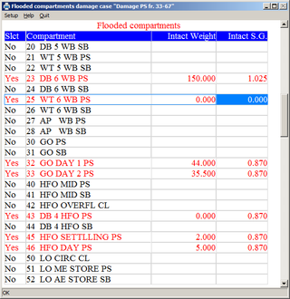
Flooded compartments per damage case, with their intact content
Generate damage cases on basis of the extent of damage
In general, damage cases are not chosen at will, they are derived from the extent of damage as laid down in rules and regulations instead. For example it can be stipulated that a ship has to survive a damage with a length of 10% of the ship's length, 1/5 of the vessel's breadth and unlimited height. Subsequently it is up to the designer to identify and define all resulting damage cases. this task can also be preformed with this PIAS function.
For this purpose, the currently discussed functionality is developped, where damage dimensions can be entered. Even multiple sets of damage dimensions, because for different regions different extents of damage can be applicable (e.g. for the forward 30% of vessel a bottom damage with a breadth of 5 meter, while for the other 70% a breadth of 3 meter will suffice). For each damage dimension can be entered:
- Description. This name is to recognize this set, and is also assigned to the damage cases generated under this set.
- Damage type. Three kinds of damage types exist: side damage SB, side damage PS and bottom damage.
- Length. The damage length, the longitudinal extent of damage.
- Penetration. With side damage this is the transverse extent of damage (measured from CWL), with bottom damage this is the vertical extent of damage (measured from the bottom).
- Dimension. With side damage this is the vertical extent of damage (which, by the way, is unlimited in most rules). With bottom damage this is the transverse extent of damage, the damage breadth.
- Aft boundary and forward boundary. These are the boundaries of applicability of this dimension set. With the mentioned example where for the forward 30% another regime applies that for the other 70%, two dimension sets have to be defined, one with boundaries aft and 70%Lpp, and the other one with boundaries 70%Lpp and forward.
Furthermore, two additional functions are available:
- [Standard]. A utility function, which can be used to calculate a standard dimension quickly. For example, a rule exists where the damage length is prescribed to be 1/3L2/3. With this function, [Standard], this equation be called and the number calculated. Because for each dimension (L, B and H) other rules apply this function works by menu cell.
- [Generate]. With this function the damage cases will be generated. Prior to that, a window pops up where the generation preferences can be specified :
- The choice of between ‘In addition to existing damage cases’ and ‘As replacement of existing damage cases’ existing damage will be obvious.
- With ‘Prevent minor damages’ the so-called minor damages — damages from which the compartments are a subset of aother, more extensive, damage — will not be generated. If such minor damages are indeed to be generated, then systematically damages are created with less than the maximum penetration from the side, however, the vertical and longitudinal directions are not systematically searched for that purpose. For the reason that in that fashion relatively large amounts of minor damages would be found. which, as a rule, might be expected to be less severe than the main damage. And although hundreds of minor damages can very well be managed by PIAS, it leaves humans with very little overview.
- Whether ‘ mutually identical damages’ should be avoided. As a rule, this will be desirable, what is after all the usefulness of multiple, identical damage cases which are inflicted from multiple directions (eg. side and bottom) ?
By the way, regulations may allow that damage to the ER, or involving ER bulkheads, are not taken into account. Nevertheless these will be generated with this [Generate] function. Such superfluous damage cases will have to be removed by the user afterwards, under the slogan “throwing away is easier then adding”. A possibly easier alternative is to use different regions of damage dimensions, using the aft and forward boundaries thereof. One has to use region boundaries slightly aft or before the ER bulkhead, otherwise that bulkhead will unintendently still become damaged.