|
PIAS Handleiding
2026
Programma voor de Integrale Aanpak van het Scheepsontwerp
|
|
PIAS Handleiding
2026
Programma voor de Integrale Aanpak van het Scheepsontwerp
|
If main dimensions have been set, including target values for block coefficient \((C_b)\) and longitudinal center of buoyancy (LCB), see Hoofdafmetingen (ontwerp) & coefficienten, Fairway enables you to design towards these targets by means of the target sectional area curve (target SAC). This action is for the construction and manipulation of a target SAC, and is started from [Hydrostatics]→[Generate/Modify Target SAC], keys <Alt><C><A> or a click on one of the points on the target SAC. The SAC can be viewed in a dedicated modelling view by selecting [Hydrostatics]→[Sectional Area Curve (SAC) Window], which also shows the hull lines as seen from below and from the side, for reference, shown in the figure below. The view also shows the actual SAC in gray, which cannot be edited and represents all buoyant solids and forms the basis for hydrostatics information; it can be updated from the hydrostatics window (see Hydrostatic Data). The SAC view is automatically brought forward when this action is started.
Once a target SAC has been created, it can be used to compare the submerged frame area during frame manipulation (see Show Target Frame Area). The target SAC, if present, is also used to base automated hullform transformation on, see [Shift Frames (Lackenby)] and [Inflate/Deflate Frames].
If a target SAC is not present yet when the action is started, the user is asked to create one by pressing one of two buttons:
The above functionality is also available during manipulation of an existing target SAC, with the buttons [Regenerate from solid] and [Regenerate from Lap] seen in the figure below.
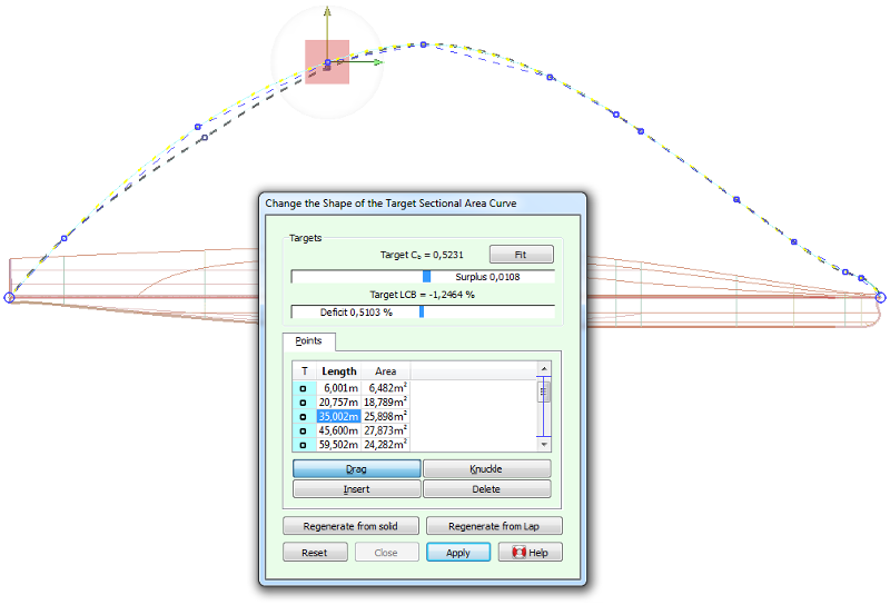
The target SAC is represented by a polycurve fitted through a number of given area values, and can thus be manipulated by changing these values; much in the same way as points can be changed on ordinary polycurves. There are four manipulation modes: [Drag], [Knuckle], [Insert] and [Delete]; their operation is completely analogous to the point manipulation modes.
During manipulation of the target SAC, two gauge bars in the action panel show how well the SAC matches the target values as specified in [Hoofdafmetingen (ontwerp) & coefficienten]. The [Fit] button here will transform the target SAC so it matches the target values, using the same algorithm as in [When designing with a target SAC].
Als men bij een scheepsontwerp begint met niks, maar wel een doelstelling heeft voor waterverplaatsing of drukkingspunt, dan kan een initiële KVS een goed hulpmiddel zijn om daar doelgericht naar toe te werken. Nu zijn er niet veel methodes bekend om een KVS te genereren, maar Lap (NSP, Wageningen) heeft daar wel over gepubliceerd. Dat zijn de z.g. Lap-diagrammen, die toepasbaar zijn of bulbloze schepen met een conventioneel kruiserhek (dus geen praamvorm). Er zou aan de scheepseinden dus een conflict kunnen bestaan tussen het spantoppervlak uit de diagrammen, en het stevencontour wat gewenst is. Zo'n conflict kan men iteratief oplossen, bijvoorbeeld op de volgende manier:
De diagrammen van Lap zijn overigens in numerieke vorm vastgelegd in een los bestand, kvslap.txt, wat wijzigbaar is zodat een gebruiker alternatieven kan gebruiken, als deze beschikbaar zijn. Bestandsformaat van tabellen t.b.v. het genereren van een KVS bevat hierover meer details.