|
PIAS Manual
2026
Program for the Integral Approach of Shipdesign
|
|
PIAS Manual
2026
Program for the Integral Approach of Shipdesign
|
If main dimensions have been set, including target values for block coefficient \((C_b)\) and longitudinal center of buoyancy (LCB), see Main dimensions (design) & hull coefficients, Fairway enables you to design towards these targets by means of the target sectional area curve (target SAC). This action is for the construction and manipulation of a target SAC, and is started from [Hydrostatics]→[Generate/Modify Target SAC], keys <Alt><C><A> or a click on one of the points on the target SAC. The SAC can be viewed in a dedicated modelling view by selecting [Hydrostatics]→[Sectional Area Curve (SAC) Window], which also shows the hull lines as seen from below and from the side, for reference, shown in the figure below. The view also shows the actual SAC in gray, which cannot be edited and represents all buoyant solids and forms the basis for hydrostatics information; it can be updated from the hydrostatics window (see Hydrostatic Data). The SAC view is automatically brought forward when this action is started.
Once a target SAC has been created, it can be used to compare the submerged frame area during frame manipulation (see Show Target Frame Area). The target SAC, if present, is also used to base automated hullform transformation on, see [Shift Frames (Lackenby)] and [Inflate/Deflate Frames].
If a target SAC is not present yet when the action is started, the user is asked to create one by pressing one of two buttons:
The above functionality is also available during manipulation of an existing target SAC, with the buttons [Regenerate from solid] and [Regenerate from Lap] seen in the figure below.
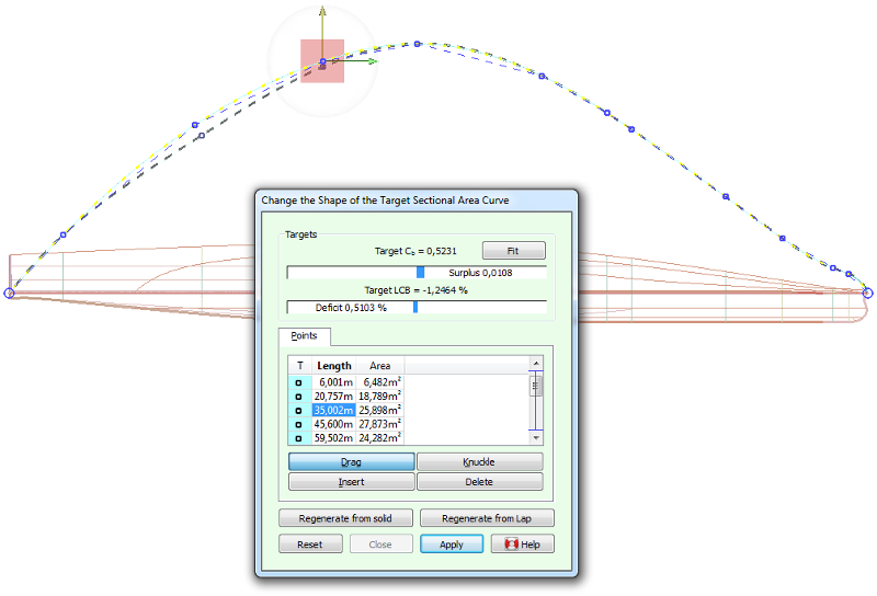
The target SAC is represented by a polycurve fitted through a number of given area values, and can thus be manipulated by changing these values; much in the same way as points can be changed on ordinary polycurves. There are four manipulation modes: [Drag], [Knuckle], [Insert] and [Delete]; their operation is completely analogous to the point manipulation modes.
During manipulation of the target SAC, two gauge bars in the action panel show how well the SAC matches the target values as specified in [Main dimensions (design) & hull coefficients]. The [Fit] button here will transform the target SAC so it matches the target values, using the same algorithm as in [When designing with a target SAC].
When commencing a ship design from scratch, with a target displacement or LCB, an initial SAC might be a proper tool to speed up this process. Unfortunately, not many methods are available to generate a SAC, although Lap (NSP, Wageningen, The Netherlands) did publish one. Those are the so-called Lap-diagrams, applicable on bulbless vessels with a conventional cruiser stern (so, no pram-type of aftship). So, at the ship extremes (for and aft) a conflict might arise between the sectional area according to these diagrams, and the desired stem or stern profile. Such a conflict may be solved iteratively, for instance in the following fashion:
The Lap diagrams are numerically contained in a separate file, kvslap.txt, which is modifyable so a user can use alternatives, if available. File format of diagrams for generation of a sectional area curve contains more information on the file format.