|
PIAS Manual
2026
Program for the Integral Approach of Shipdesign
|
|
PIAS Manual
2026
Program for the Integral Approach of Shipdesign
|
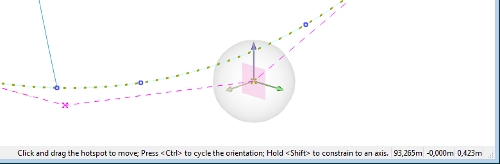
Whenever a position can be manipulated graphically, a so-called dragger appears in the modelling views. It consists of one or more arrows contained in a translucent sphere that loosely resembles a soap bubble. This sphere marks the dragger “hotspot”: to interact with the dragger you need not aim precisely at the arrows, it suffices to click on the hotspot and start dragging.
The dragger attaches to a movable entity such as a point or vertex, and thereby gives a handle on its position. If there are more than one movable entities in the view, then the dragger jumps to the one that is nearest to the mouse pointer, so it is easy to switch focus between them.
Whenever a dragger is present, its three-dimensional coordinates are displayed in the right end of the status bar, along with a concise usage instruction.
The arrows of the dragger indicate the positive directions of the freedom of motion. If there is just one arrow then it can only be dragged linearly along a single axis. If there are two arrows then dragging is possible in the plane that contains the arrows, which is also indicated by a small square at the center of the dragger. If the dragger is attached to an entity that is free to be positioned in three dimensions, then this is indicated by a third orthogonal arrow. The third arrow is transparent to indicate that it is inactive. By holding the mouse pointer over the hotspot and pressing <Ctrl> you switch to a different pair of arrows, changing the plane of motion. The square in the middle marks the current plane.
If a dragger has more than one arrows, you can constrain motion linearly along one of the arrows by holding <Shift> while pressing the mouse button. This selects the arrow that is closest to the mouse pointer, as indicated by a dash-dotted line.
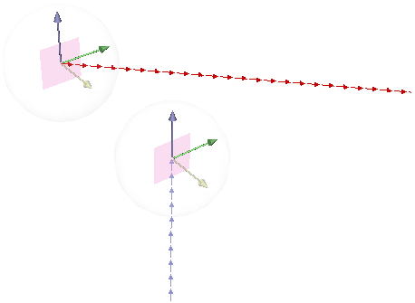
Sometimes an entity's freedom of motion does not coinside with the main axes, as is the case for points on a curve that is defined in an oblique plane. In that case, arrows are displayed that each are contained in the oblique plane and in one of the main planes. These are then coloured according to the respective main plane. So if, for example, you would hold <Shift> and drag the waterline-coloured arrow (red by default) you would move the dragger horizontally. Draggers of this type can have three arrows, but they are all coplanar. Also, the plane in the middle of the dragger is cropped by a cube, making it possibly six-sided, so its edges still run parallel to the main plane, helping you to interpret its orientation.
So the direction of motion is independent from the view direction; it is solely under the control of the dragger. There is a chance however, that one arrow is close to parallel to the view direction, or that the view direction is close to being collinear with the current plane of the dragger. This could cause excessive translation in the view direction, and to prevent that, motion is automatically constrained to the other arrow if there is one, or fully constrained otherwise. An arrow that is made inactive this way will be transparent to indicate that freedom of motion does exist in that direction, but that the view direction must be changed before it can be moved accordingly. Also, whenever a dragger is being dragged while there is a view point induced constraint, an attention notice is given in the status bar.
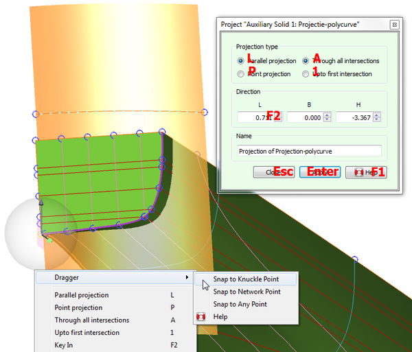
Sometimes a position needs to exactly coinside with or be aligned with another point that is already present in the model. A faster alternative to keying in the coordinates manually is to bring up the context menu by clicking the right mouse button over the dragger. You will see a sub-menu called [Dragger], containing three options:
When a point is highlighted, a dash-dotted line is drawn from the current position to where the dragger wil travel. If the dragger is not free to translate in any direction, this might not coinside with that point. This makes it possible to align a point in say, a frame, with another point in another frame, in height and breadth. This line of travel is color-coded according to its direction, using the colors associated with the main planes and axes. When the line is not parallel to any of these, then it will be colored like a curve in an oblique plane.
The coordinates displayed in the right end of the status bar normally indicate the current position of the dragger. But when snapping to other points they indicate the position that the dragger would translate to, for the currently highlighted point.
Besides the manipulation of positions, in some actions Fairway allows the manipulation of a direction represented by a vector. Instead of requiring that the vector is always defined at a fixed origin, Fairway defines the direction as the difference between two positions that can be manipulated independently. The vector is displayed as a string of small arrows such that the direction is clear, and if it coinsides with one of the main axes or main planes it adopts the corresponding color. An ordinary dragger jumps to the start or end of the vector, whichever is closest to the mouse pointer, by which respectively the whole vector can be moved or its direction can be changed. By snapping the dragger to existing points in the model as explained above, it is easy to measure directions and angles in the model.
It is possible to customize the dragger. For exampple, when producing illustrations it may be desirable to adjust the dragger to a white background. Technically confident users are referred to Customizing the dragger appearance (advanced) for instructions and examples.
Read on to learn about Modelling Actions.