This module calculates the minimum freeboard according to the International Convention on Load Lines for type A or type B vessels.
Introduction
The following regulations from the ICLL are included:
- Chapter I (general):
- regulation 3, § 1, 4, 5, 6, 7, 8 and 10.
- regulation 4.
- regulation 5.
- regulation 6, § 1, 2a up to 2f.
- Chapter III (freeboards):
- regulations 27 up to 31.
- regulation 33.
- regulation 34, § 1.
- regulation 35, § 1 up to 3.
- regulation 36, § 1g, 1h, 2 and 3.
- regulation 37.
- regulation 38, § 8 up to 12 and 14 up to 16.
- regulation 39, § 1 and 5.
- regulation 40, § 1, 3, 5 up to 7.
Prior remarks, and disclaimer:
- For the correct application of this module it is strongly advised to consult the regulations from the International Conference on Load Lines. This module does not pretend to make the use of the Load Lines Convention text redundant.
- The regulations which are not included in this module should be manually processed and accounted for.
- Parameter definitions in this module in general deviate from the PIAS standard, because the Load Lines Convention definitions prevail.
- All units are in meters, except for the bow height and sheer, which should be given in millimeters.
Main menu
Having started up loadline, one enters the main menu, the various options of which are explained in more detail in the following sections.
Main dimensions and other input parameters
The primary parameters are specified in this menu. A number of parameter can be derived from data that is already available in PIAS, that is to say, if a hull shape has been defined with Hulldef or designed with Fairway. If that is desired, in the last column ‘from hullform’ can be given (in contrast to ‘own value’, which allows the parameter to be entered manually). This is the same mechanism as used in Resistance to distill shape parameters from the hull form. Many parameters will speak for themselves or are defined in the Loadline Convention. Others are explained below.
Pre/post 2005 legislation
In 2005 the legislation has been revised, and this switch you can choose to apply either the old (pre 2005) or the present (post 2005) rules.
Depth
At the definition of the depth there is a difference between the setting before and after 2005. Pre 2005 the depth can be given in two fashions:
- With the switch ‘determination depth’ set to ‘manual’: enter the depth according to regulation 3(6) as well as the depth at 85% of the minimum moulded depth.
- With the switch ‘determination depth’ set to ‘constructed’: enter the moulded depth, the thickness of the deck stringer plate and the thickness of the exposed deck sheating (T) according to regulation 3(6a). The depth at 85% of the moulded depth is then computed with the value of the moulded depth.
If the first method is used, the cells for thickness of the deck stringer plate and the thickness of the deck sheating and the moulded depth are grayed. If the second method is used and the thickness of the deck sheating does not equal zero then a questionmark is displayed at the depth if the total length of the superstructures is not yet known.
Bow height
The bow height is defined on the forward perpendicular, in millimeters above the waterline corresponding to the assigned summer freeboard. With setting ‘pre 2005’ if the bow height is given by the user it will be verified aginst the minimum required bow height. When a height of zero is entered, the program will compute the minimum bow height, which will be included on the output. With the ‘post 2005’ setting the bow height is no user input; it will simply be computed and printed by the program.
Miscellaneous freeboard parameters
- If the facility to derive the hull parameters from the hull form is not used — but, why should one not want to use that? — the waterline coefficient of the foreship can be found in extended hydrostatic table of Hydrotables.
- A reduction percentage on the base freeboard according to reg. 27 (the so-called B-60 freeboard) can be given, as well as the allowance according to the same regulation, however, both are mutually exclusive.
- At ‘classification society’ the two characters of the classification society or national authority can be given, those will be plotted into the Plimsoll mark. With this purpose the number of letters is limited to two: one at each side of the Plimsollmerkcircle.
- With ‘plot Plimsoll mark’ to ‘yes’ a plot of the Plimsoll mark is added to the tabular output.
Superstructures
In this menu the parameters of the superstructures can be given, where each superstructure should comply with the requirements of reg. 3(10). To determine the effective length (E), the breadth of each superstructure is tested to be at least 92% of the local breadth of the ship or 60% in the case of a trunk. The height of a forecastle or poop is measured at the perpendicular when the sheer correction should be applied. For determination of the effective length of a superstructure the height must be the minimum height of the superstructure, according to chapter 1, reg. 3(10). Superstructure parameters to enter are:
- Name
- A textual description, just for identification.
- Type superstructure
- This column defines whether the superstructure is a forecastle, poop, trunk, raised quarterdeck or other type of deckhouse (‘general superstructure’). This distinction is necessary in relation to the regulations 31 and 38 (depth correction and sheer correction) and regulations 35 and 36 (effective length of superstructure).
- Breadth ship
- For each superstructure, here the ship breadth at mid-length of the superstructure should be given. If the breadth of a superstructure equals the local breadth of the ship, you may choose to use [Breadth] in order to make the superstructure breadth equal to the local ship breadth.
- Sheer correction
- If a poop or forecastle should be taken into account for determination of the sheer correction, thie column must be set to ‘yes’
- In eff.length
- If a superstructure should be taken into account for determination of the effective length of superstructure, which generally is the case, this column ‘yes’.
- Length>0.6L
- Should be set to ‘yes’ if the superstructure length is more than 0.6L. Only applicable to a ‘general superstructure’.
- Amidship
- Should be set to ‘yes’ if the superstructure extends over amidship. Also only applicable to a ‘general superstructure’.
If only one superstructure is present, of the type trunk, the length of the trunk should be at least 0.60L to be taken into account. The length of a superstructure is the length within the length between perpendiculars according to reg. 3(2).
Points of the sheer line
Here a menu appears where the height of the sheer line can be given on the six standard ordinates — APP, 1/6LPP, 1/3LPP, 2/3LPP, 5/6LPP en FPP. The standard sheer profile according to regulation 38(8) can be generated with [Standard sheer]. The sheer is measured in millimeters, as defined in reg. 38 (i.e. relative to a straight line, parallel to the construction waterline, passing through the sheer line at midship).
Calculate freeboard with output to paper
Will speak for itself, an example of the output is presented below.
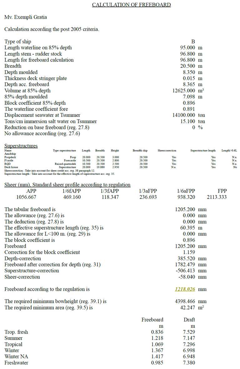
Freeboard computation details in the output.
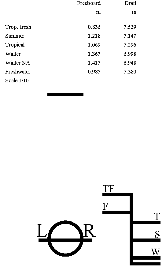
Plot of Plimsollmerk in the output.
File and backup management
Backups of the input data can be made and restored here. Here is also the option ‘Stop without saving’. See for the details Data storage and backups.