With this module resistance predictions can be made for different ship types, with nine published empirical methods, viz:
- Hollenbach, for displacement vessels.
- Holtrop & Mennen, for displacement vessels.
- Van Oortmerssen, for smaller displacement vessels.
- Britisch Columbia, for smaller displacement vessels with a low L/B ratio.
- MARIN for barges.
- Mercier & Savitsky for vessels in the transition region between displacement and planing mode. A.k.a. preplaning range.
- Savitsky, for planing chine vessels.
- Robinson, for planing chine and round bilge vessels.
- Keuning, Gerritsma & van Terwisga, for planing chine vessels with large deadrise angle.
Overview and applicability of the calculation methods.
- Note
- In this section for each method the applicability and ranges of validity are given. It will be evident that if parameters fall outside these ranges, the results will be unreliable. But even apart from that one should realise that all applied resistance prediction methods used are based on statistics, so it is recommended to always take a critical look at the results.
Hollenbach
With this method a resistance approximation is made for the displacement condition. The approximation is based on Dr.Ing. Uwe Hollenbach, SDC Ship Design & Consult GmbH, Germany, “Estimating resistance and propulsion for single-screw and twin-screw ships in the preliminary design” 10th International conference on computer applications in shipbuilding, 7–11 June 1999. The parameters should be within the following limits:
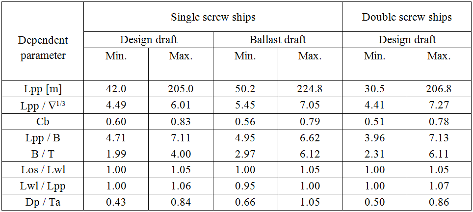
Hollenbach limits of applicability.
Holtrop and Mennen
This method approximates the open water resistance according to the following publications:
- J. Holtrop & G.G.J. Mennen “An approximate power prediction method” International Shipbuilding Progress, 1982.
- J. Holtrop “A Statistical re-analysis of resistance and propulsion data”, International Shipbuilding Progress, 1984, pp.272–276.
The parameters should be within the following limits:
- The approximation is valid for seawater (1.025 ton/m3) of 15° Celsius, for calm water.
- Cross-sectional area of the bulb must be less than 20% of the miship sectional area.
- Midship coefficient between 0.5 and 1.0.
- Lwl/B ratio between 3.5 and 9.5.
- LCB between -5% and +5% of Lwl/2.
- Prismatic coefficient between 0.40 and 0.93.
- Half angle of waterline entrance maximum 70°.
- Resistance coefficient of bow propeller between 0.003 and 0.012.

Holtrop and Mennen.
Oortmerssen
This methode makes an estimation of the resistance of a vessel according to G. van Oortmerssen, “A Power Prediction method and its application to small ships”, International Shipbuilding Progress Vol.18, no 207. The parameters should be within the following limits:
- Froudenumber (= V / √(g × Lwl) where V = speed in m/s, g = 9.81 m/s2, Lwl = length waterline in m) between 0 and 0.5.
- Length between perpendicular between 9 and 80 m.
- Wetted area between 0 and 1500 m2.
- Volume between 0 en 3000 m3.
- Long. centre of buoyancy between -8% and 4% of Lpp before half Lpp.
- Prismatic coefficient between 0.5 and 0.73.
- Half entrance angle waterline between 10° and 46°.
- Breadth / draft ratio between 1.9 and 4.0.
- Midship coefficient between 0.72 and 0.97.
- Length / breadth ratio between 3.0 and 6.5.
- Water density between 1.0 and 1.03 ton/m3.
- Appendage coefficient (= multiplicationfactor for the volume to get to volume & appendages) between 1.0 and 1.10.
British Columbia
This method can be used for the somewhat smaller vessels with a small length / breadth ratio. The method is based on Dr. Sander M. Çalişal & Dan McGreer, University of British Columbia, Vancouver, BC, Canada. “Model resistance tests of a systematic series of low L/B vessels” A paper presented to the spring meeting of the Pacific Northwest section of the society of naval architects and marine engineers. The parameters should be within the following limits:
- Froudenumber (= V / √(g × Lwl) where V = speed in m/s, g = 9.81 m/s2, Lwl = length waterline in m) between 0 and 0.5.
- Wetted area between 0 and 1500 m2.
- Volume between 0 en 3000 m3.
- Blockcoefficient between 0.531 en 0.614.
- Breadth / draft ratio between 1.5 and 3.5.
- Length / breadth ratio between 2.0 and 4.5.
- Water density between 1.0 and 1.03 ton/m3.
- Appendage coefficient between 1.0 and 1.10.
Barge
This method can be used to approximate the resistance of a barge. The calculations are according to the method described in MARIN report no.49791-1-RD, “Een empirisch model voor de weerstandspredictie van bakken”. The prediction is valid for deep and calm water, and has the following applicability:
- Froudenumber (= V / (g × breadth)1/2, where V = speed in m/sec and g = 9.81 m/sec2) smaller than 0.60.
- Length / breadth ratio between 2.25 and 8.0.
- Breadth / draft ratio smaller than 10.
- Prismatic coefficient between 0.7 and 1.
- Length of fore body, with a minimum of 0.01 m on model scale (note: at SARC this is considered to be a bit curious criterion, for what would be the ‘model scale’ of a scale 1:1 barge? But anyway, this is how it is listed in MARIN's publication).
Preplan
With this method you can calculate the resistance of a vessel in the area between displacement and planing condition. The calculations are according to the method as published in J.A. Mercier & D. Savitsky, “Resistance of transom shear craft in the pre-planing range”, Davidson Labatory Report 1667, Stevens Institute of Technology, June 1973. The method has the following area of applicability:
- Froude number based on the volume (= V / √(g × (volume1/3)) where V = velocity in m/sec, g = 9.81 m/sec2, volume = volume in m3) between 1 and 2.
- Half angle of entrance of the waterline between 10° and 55°.
- Ratio length / volume1/3 between 2 and 12.
- Ratio transomarea / maximum cross-sectional area between 0 and 1.
- Ratio length / breadth between 2 and 14.
- Water density between 1.00 and 1.03 ton/m3.
- Appendage coefficient between 1.0 and 1.10.
Savitsky
With this method you can calculate the resistance of a planing hull. The method is based on the following two publications:
- D. Savitsky “Hydrodynamic design of planing hulls”, Marine Technology, Vol.1, No.1, Okt. 1964, pp. 71–75.
- Donald L. Blount & David L. Fox “Small craft power prediction”, Marine Technology Vol.13, No.1, Jan. 1976, pp. 14–45.
For the resistance calculations all forces are assumed to go through the centre of gravity of the vessel. For calculations in the preliminary design stage this is assumed to be sufficiently accurate. The output shows two values for the resistance:
- Resistance according to Savitsky which is valid for test conditions.
- Corrected resistance for true operational conditions according to the method of Blount and Fox. This method calculates two correction factors:
- Correction for test resistance to true operational resistance for the naked hullform.
- Correction for the influence of appendages.
The method has the following area of applicability:
- Rise of floor (deadrise angle) between 0° and 35°.
- Density of water between 1.00 and 1.03 ton/m3.
- Appendage coefficient between 1.0 and 1.10.
- Speed ratio Cv (= V / √(g × Bpx), with V = speed in m/sec, g = 9.81 m/sec2 and Bpx = maximum knuckle breadth in m) between 0.6 and 13.
- Length of wetted keel / maximum knuckle breadth larger than 4, this implies that the length on the waterline / maximum knuckle breadth larger is than 4.
Robinson
With this method the resistance of a planing vessel can be calculated. The method is based on John Robinson, Wolfson Unit MTIA, University of Southampton, “Performance prediction of chine and round bilge hull forms”, Hydrodynamics of High Speed Craft, 24 and 25 November 1999, London. The following limits for the parameters have to be taken into account:
- Volumetric Froude number between 0.5 and 2.75.
- See following figures:
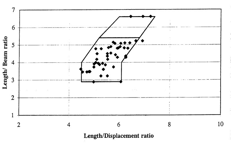
Hard chine regression data boundary
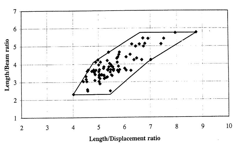
Hard bilge regression data boundary
Delft
With this method the resistance of a planing vessel can be calculated. The method is based on J.A. Keuning, J. Gerritsma and P.F. van Terwisga, “Resistance tests of a series planing hull forms with 30 degrees deadrise angle, and a calculation model based on this and similar systematic series”, International Shipbuilding Progress 40, No.424, (1993) pp. 333–385. The following parameter limits have to be taken into account:
- Volumetric Froude number between 0.75 and 3.00.
- Volume between 2.5 and 5000 m3.
- Rise of floor (deadrise angle) between 12.5° and 30°.
Shallow-water correction
A shallow water correction method has been implemented, based on H.C. Raven, “A new correction procedure for shallow-water effects in ship speed trials”, Proceedings of PRADS2016 (2016), Kopenhagen, Denmark. In 2017 the ITTC has accepted this method: International. Towing Tank Conference, “Report of specialist committee on performance of ships in service”, Proceedings of 28th ITTC (2017), Wuxi, China. .
Raven's method has been implemented for five of the resistance prediction methods: Hollenbach, Holtrop and Mennen, Oortmerssen, Barge and British Columbia.
The method knows the following limits of applicability:
- Froude depth number lower than 0.65.
- Draft / water depth ratio below 0.5.
- Displacement increase due to additional sinkage below or equal to 5%.
Main menu
Input data resistance prediction
In this window all ship's parameters which are applicable for a certain method should be given. In the list below all existing parameters are included, however, in reality only those relevant for a particular method are shown. The definition of all parameters is strictly according to the convention of the applied resistance prediction method, which does not have to agree with the PIAS convention. Below, some guidance on these conventions is given, nevertheless it is recommended to keep the source publications at hand for the details.
- Method: the chosen resistance prediction method.
- Name and Identification name: just for identification purposes
- Density of the water, in ton/m3.
- Ship type: choice between single / twin screw vessel, or chine / round-bilge vessel (dependant on the selected prediction method).
- Length of underwater body: see figure below.
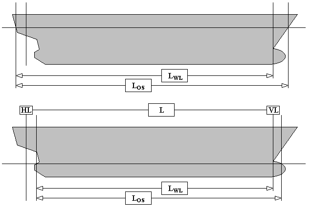
Definition of lengths for the Hollenbach method
- Length waterline and length between perpendiculars: The aft perpendicular is the center of the rudder stock, the forward perpendicular is the intersection of the waterline and the stem. Length between perpendiculars is the distance between those perpendiculars, length waterline is the distance between the forward perpendicular and the intersection between waterline and the stern, as depecited in the figure below.
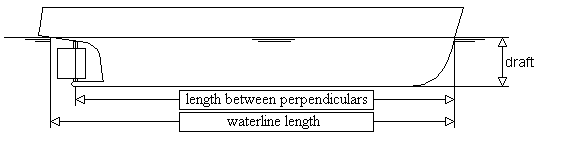
Definition length for the Oortmerssen method.
- Length of forebody: length LKOP, see figure below.
- Length of non-prismatic aftbody: length LST, see figure below.
- Draft for calculation: choice between design and ballast-draft.
- Mean draft: the vertical distance between the baseline and the waterline at half the waterline length.
- Wetted surface: the wetted surface area of the hull form that is under the waterline.
- Midship coefficient to be determined on the largest cross-sectional area.
- Waterline coefficient: If yet unkown, it can be roughly approximated by 1/3 + 2/3 × block coefficient.
- Prismatic coefficient of aftbody: should be given for the non-prismatic part of the aftbody.
- Angle of aftbody buttocks to the baseline: angle αST, see figure below.
- Radius flat bottom-aftbody: radius RST, see figure below.
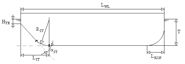
Definitions for the Barge method.
- Half entrance angle of the waterline: the half entrance angle of the faired waterline, without the local stem correction.
- Longitudinal centre of buoyancy: defined as an percentage of the waterline length, relative to half waterline length, positive forward and negative aft.
- Cstern: the CSTERN shape coefficient value from the tables below.
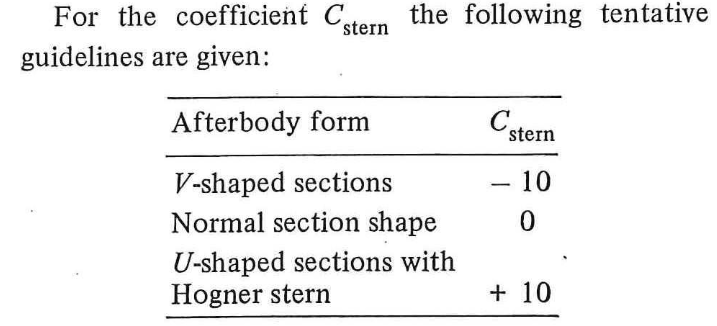
The Cstern table from the Holtrop & Mennen paper.
- Appendage coefficient: the appendage area (in m2) as well as the resistance coefficient (labelled ‘1+K2’) according to the table below. For a composition of multiple appendages, the weighted average of the 1+K2 coefficients should be taken.
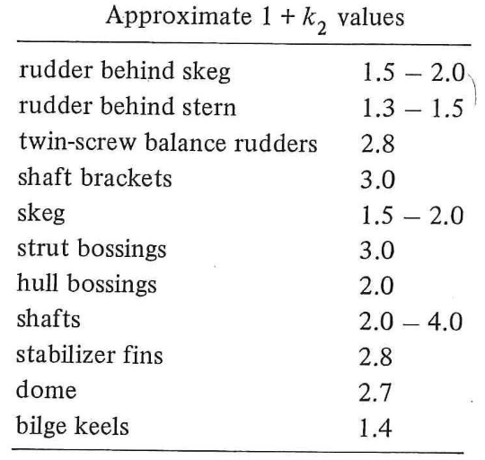
The 1+K2 table from the Holtrop & Mennen paper.
- Submerged transom area: the submerged transom area (in m2).
- Mean immersion depth of the transom: Mean immersion depth of the transom HTR. See figure of “Definitions for the Barge method”.
- Number of bow thrusters: the number of bow thrusters, in combination with the diameter (in m) and resistance coefficient (between 0.003 and 0.012) for every bow thruster opening.
- Bulb: choice between bulb or no bulb. With the cross-sectional area at FPP (in m2) of the bulbous bow and the VCG (in m) of this cross-sectional area from baseline.
- Planing length: length of the projected planing bottom area.
- Planing breadth: breadth over the chines.
- Planing area: projected planing bottom area.
- Twisted bottom: choice between twisted bottom or no twisted bottom.
- Twist angle: difference in rise of floor between foreship and aftship.
- Centreline angle: average angle between centreline and baseline, over the aft half of the ship. Positive if draft aft is greater than draft at half length.
- Breadth: for method Robinson the breadth over all. For other methods, moulded breadth of the ship.
- Breadth at chine: the breadth of the ship at chine.
- Volume including shell & appendages: the volume of the ship including the volume of the shell and appendages.
- Moulded volume: the moulded volume of the ship.
- Model ship correlation coefficient: is a coefficient which is used to get from specific method scale model values to real life scale.
- Submerged cross section area: the submerged cross section area.
- Longitudinal centre of gravity: is the location of the centre of gravity in longitudinal position, measured from the transom along the keel line of the ship.
- Rise of floor: in a cross section, the angle between the baseline and the bottom. Deadrise angle.
- Speed interval: at which interval, between start speed and end speed, the resistance will be calculated.
- Input air resistance: choice between with or without air resistance.
- Projected area air resistance: the projected area which is subjected to air resistance.
- Stabilisation vins: choice between with or without stabilisation vins.
- Wetted surface area stabilisation vins: the wetted surface area of the stabilisation vins.
- Bilge keels: choice between with or without bilge keels.
- Wetted surface area bilge keels: the wetted surface area of the bilge keels.
- Dome: choice between with or without dome.
- Wetted surface area dome: the wetted surface area of the dome.
- LCG relative to half length of planing area: in percentage, positive forward and negative aft.
- Waterdepth: The waterdepth in meters that is used for the optional shallow water correction. Must be at least twice the draft.
Besides the columns for specifiying the parameter velues, this menu contains at the right side a column labelled ‘source’, which can be:
- User-defined: a value given by the user.
- From hullform: the parameter value of this line is extracted from the PIAS hullform (as defined with Fairway of Hulldef).
- Estimation: this parameter is to be determined with empirical estimation equations, which are available in some resistance methods. Obviously, this option (as well as ‘From hullform’) is only applicable to rows where supporting functions are indeed available for the corresponding parameters.
- Attention
- With the ‘From hullform’ option one should realize that a Hulldef ship hull representation contains sections only. This implies that the waterline extremities are not exactly available, because they will in general fall between two sections. PIAS uses extrapolation to estimate the waterline shape in those regions, however, it is advised to verify the waterline-oriented parameters — typically ‘Half entrance angle of the waterline’ and ‘Length waterline’ — well and correct if neccessary. It will be obvious that this warning evaporates a bit with a dense frame set, e.g. as can be generated with Fairway.
Calculate and print
For the parameters as given at the first menu option, here the resistance approximation is made, and the results are printed in a table.
Diagram of resistance components
Similar to the previous option, with the resistance and its components plotted in a graph.
Calculate and send to Propeller
The input data as well as the calculated resistance is sent to the propeller calculation module Propeller.
Local cloud monitor
See Local cloud: simultaneous multi-module operation on the same project.
File and backup management
With this option design version can be managed, with a mechanism as described in Data storage and backups.