|
PIAS Manual
2026
Program for the Integral Approach of Shipdesign
|
|
PIAS Manual
2026
Program for the Integral Approach of Shipdesign
|
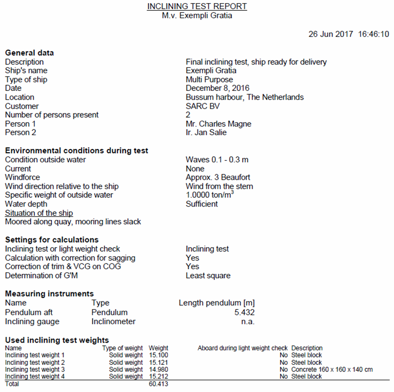
Here the general data of the inclination test or light weight check can be given, from which quite some will speak for themselves. That is just textual input — such as for ‘Condition outside water’ or ‘Number of persons present’ — which can be given and which will be printed on the measurement report. However, a number of calculation settings require some elucidation:
This is the density (the specific weight) of the outside water (in ton/m3) during the inclination test or light weight check, so it is not related to the design density as given in Density outside water.
Here is defined what type of calculation is made and thus what type of report is generated. Furthermore it should be noted that, when an inclining test is selected but only the zero measurement is defined or there are no test weight defined at the zero measurement, that automatically a light weight check is calculated.
With this switch the method of calculation of the volume (and hence the weight during the inclining test or light weight check) and Longitudinal Center of Buoyancy can be chosen. Obviously, sagging can only be taken into account when drafts/freeboards have been measured at at least three locations. At a calculation without correction for sagging a straight waterline is determined as close as possible to the measured drafts. At a calculation with this correction a parabolic waterline is constructed. In both cases the waterplane construction is done with the least squares method.
Please read for the background of this issue first the discussion at ‘With free-to-trim effect, including the effect of VCG on trim’, see Stability calculation method. The point is that trim & VCG on the one hand, and LCG & TCG on the other hand have a mutual relationship. In conventional calculations this effect was taken into consideration, but here in PIAS it can be incorporated. If one should wish the results of the elaboration of the inclining test to be fully compatible with those of the loading conditions, then this setting here in Incltest should be set the same as the referred setting in Config. Please note that if the ship has a heel angle during the light weight check then it is advised to use this option.
If this ‘Correction of trim & VCG on CoG’ is switched on, the VCG should obviously be known. When elaborating an inclining test that is always the case, because then the VCG is just computed! However, when only a light weight check is done, then the VCG is not known, so it must be user-specified, which can be done here. If the VCG is not known exactly, then one should be satisfied with an estimation.
If the vessel's hydrostatics remain constant throughout the inclining test, the 'Conventional' option can be selected, whereby the overall G'M is determined in 1 time from all measurements using the least squares method, and the VCG is calculated using the KM of the zero measurement. If the hydrostatics are not constant, the 'Non-conventional' option can be chosen where the VCG is calculated per measurement with the actual KM and FSM of that measurement. The KM may differ if there is a difference in waterline surface even at small angles, and the FSM may start to differ if tanks are used as inclining test weights. Also, when tanks are used, the displacement may not be constant, and the VCG of the inclining test weights itself may change. The latter may also be applicable for fixed inclining test weights.
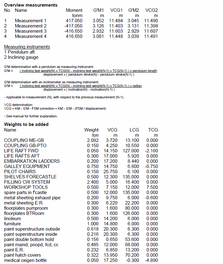
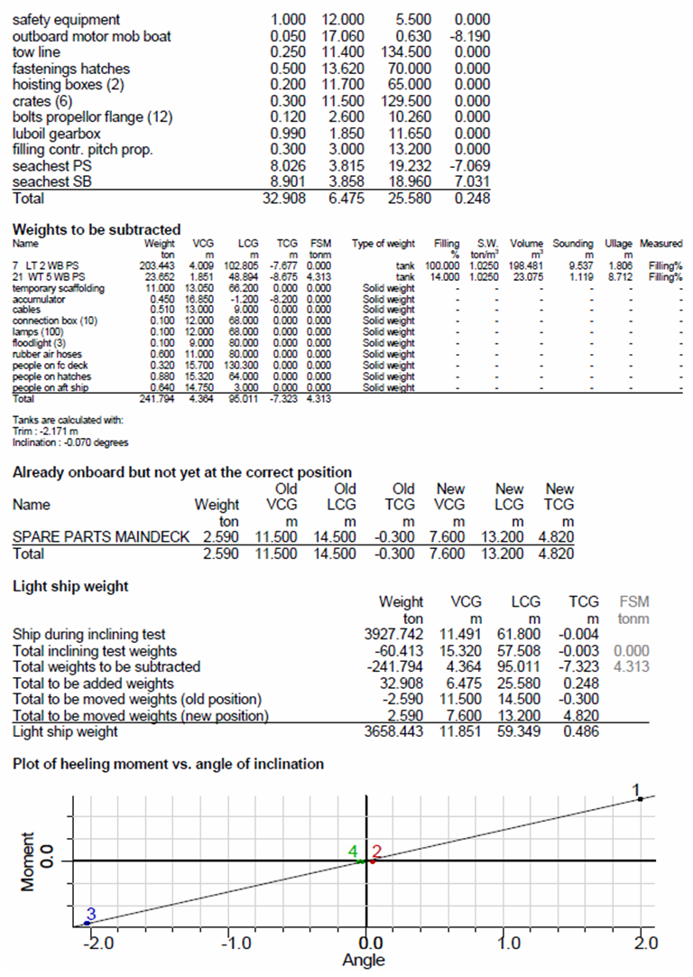
At an inclining test, multiple measurements of G'M are performed. From these measurements the single resulting G'M must be determined. The probably most evident method is to take the mean of all measurements. An alternative comes up if we plot the measured angles of inclination against the heeling moments — such a graph is included in the inclining test report as produced by Incltest. If, subsequently, a straight line is drawn through these points, the inclination of this line represents G'M. That straight line is being determined by the least squares method, so this is also the name of this method. If the option 'Conventional' is selected, this method will always be used.
The output of Incltest may contain a side view of the ship, where draft, trim and sagging are depicted. For such a sketch a wind contour can be used — as discussed in Wind contour — and at this setting one may specify which contour to use for this purpose.
This is a simple form where inclination gauging particulars can be given. PIAS support ten such devices, of three types:
This table contains the heart of the matter, here the measurements are being entered in PIAS. The first row is always present in this table, which is the so-called “zero measurement”, which fixes the initial condition. For each measurement there is one line, which contains:
With the text cursor on the row of a measurement, one can with <Enter> continue to input forms of freeboards/drafts and inclining test weights, as dicussed just below.
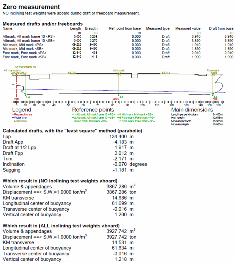
This is the input form of freeboards and/or drafts, which contains seven columns:
With [New] one always creates a ‘Reference point’. For reading on a draft mark the function [Draft marks] is available. With this function one can read draft marks, as defined in PIAS as discussed in Draft marks and allowable maximum and minimum drafts. If the specific measuring point is a draft mark then the columns 1 to 5 have been filled with data from the defined draft mark and for that reason cannot be modified.
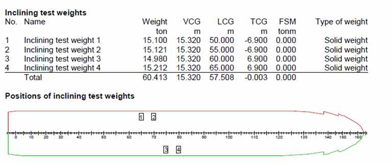
In this form the inclining test weights are defined. At the zero measurement inclining test weights can be added or removed, in all the other measurements only specific data can be changed. Inclining test weights which have been create in the zero measurement are available in all the other measurements.
In PIAS two types of inclining test weights are supported, a conventional solid weight (such as a block of concrete or a barrel filled with water), or a tank. From each inclining test weight should be given:
With [New] one always creates a test weight of type ‘solid weight’. For adding weights of type ‘tank’ the function [Tank list] is available. Here is a list of all the tanks that can be used as a test weight. This function does the same as the function with the same name in Loading — which is discussed in Define/edit weight items under function [Misc].
The particulars to be entered for a specific type of test weight are:
When conduction an inclining test or light weight check, not each and every weight will be on its final position. In practice always some weight adjustments will have to be made, commonly called weights to add or to deduct. That can be done by this menu option, which is subdivided in three catagories.
Weight to be added to light ship, where for each weight item the name, weight and CoG should be given.
Weight, present on board during the test, not belonging to light ship. Just as with the previous category this can be simply unconnected items, with name, weight and CoG. However, one can also use the function [Tank list], as described in Locations of inclining test weights, to add weights of type tank, as defined in PIAS (with Layout). If feasible, this feature is certainly convenient to use, because then giving just a percentage of filling, or sounding or ullage will suffice, and be used to calculate volume and CoG of the tank content, taking into account heel and trim.
Weights, present on board during the test, but not yet on their final position. In this menu for each item the weight should be given, as well as its position during the test as well as the final position in light ship.
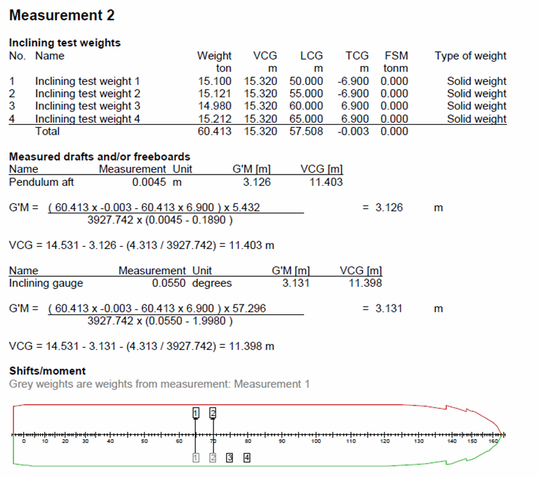
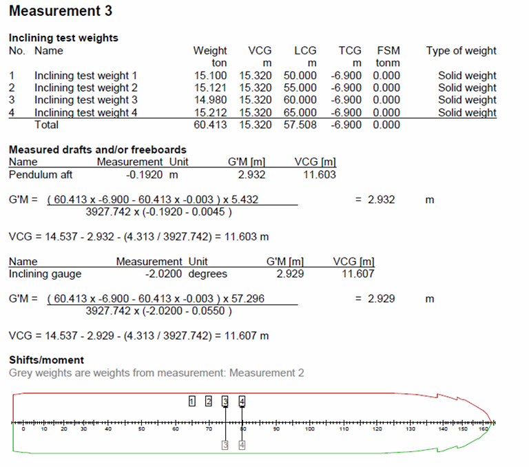
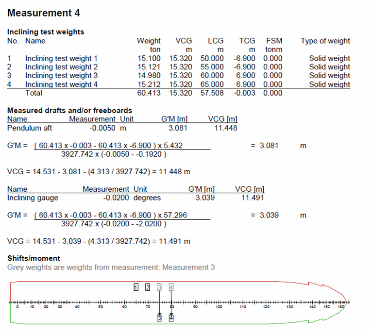
Prints the inclining test or light weight check report, below an example is included of the output with the option 'Non-conventional'.
Backups of inclining test data can be be made and restored here, please refer to Data storage and backups for more details.
Prints an inclining test report or light weight check report, according to the method as being applied by PIAS until december
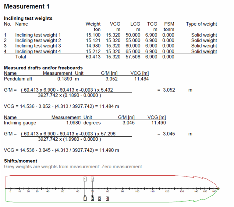
The following applies to the "Non-conventional" option, for the "Conventional" option the calculation of the G'M and VCG is in the output.
For a pendulum measurement applies:
\( GM = \frac {(Testweight_N . TCG_N - Testweight_{N-1} . TCG_{N-1}) . Pendulumlength} {Displacement . (Pendulumstroke_N - Pendulumstroke_{N-1}) } \\[6pt] \)
and for an inclinometer:
\( GM = \frac {(Testweight_N . TCG_N - Testweight_{N-1} . TCG{N-1}) . 1 Radian} {Displacement . (Inclinationangle_N - Inclinationangle_{N-1}) } \)
The vertical center of gravity (VCG) is computed by:
\( VCG = KM - G'M - GG' = KM - G'M - \frac{FSM}{displacement} \\[6pt] \)
where:
The design of the original version of Incltest was drawn up around 1988. In the course of the years, quite some changes and extensions have been made, but the basic structure has roughly remained the same. Comments and desires of many users have been collected over the years, and haven been used in the implementation of a completely new module which replaced the elder one in December 2016. Many of these changes do not affect the basic methodology of input and calculation, however, there is one essential difference that needs to be explained in more detail:
In the elder Incltest module the movements of the inclining test weights as well as the pendulum stroke or measured inclination were given with respect to the previous measurement. In this new module the positions of the inclining test weights are given in the ship's coordinate system, and the stroke / inclination relative to the zero measurement. With old inclining test data, movements and pendulum strokes are in first instance interpreted in the old way, so that the calculation yields the same results as previously. All the old inclining test data can be found in File management. Old measurement reports, if available, can be printed with the menu option Print pre-2017 measurement report. If one would like to use the old inclining test data then one can restore the data with use of Restore data from backup. The restored data is then immediately interpreted in the new fashion, and the calculations will (consequently) no longer be correct. One should now re-enter movements and strokes in the new convention.
It is not possible to, proceed according the old method, and newly defined inclining test data cannot be interpreted upon the old method.