PIAS Manual  2024
Program for the Integral Approach of Shipdesign
Inclmeas: registration and processing of digital inclination measurement
This module measures the inclination during the inclining test. For every measurement you can specify the translation and size of the test weight. The measurements can be exported to the inclining test report module. Furthermore it is possible to present a graphical representation on the screen or send it to a printer.

Guidelines for installation

The inclination sensor is equipped with a USB cable, which is used to connect the sensor to the computer. It is required to install the driver which belongs to the sensor. The sensor can be placed in an arbitrary place in the ship, however, the underground should be firm. During measurement the sensor should not wiggle or be relocated.

inclmeas_example_inclining_measurement800.png
Digital inclining measurement

Main menu

Test measurements

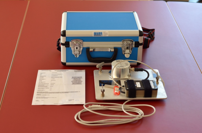
The module reads out the serial port and the results are printed on screen. The presented angles are the angles of both axes of the measurement gauge box. The range of the gauge is -5 to + 5 degrees. Thus the gauge must be positioned such that the measurement values lie within the limits. Besides checking whether the gauge is positioned correctly, the gauge can be used to check the weight displacement that is necessary to realize a certain inclination (for example 1 degree).

inclmeas_test_example.png
Real time graphic

Inclination measurement

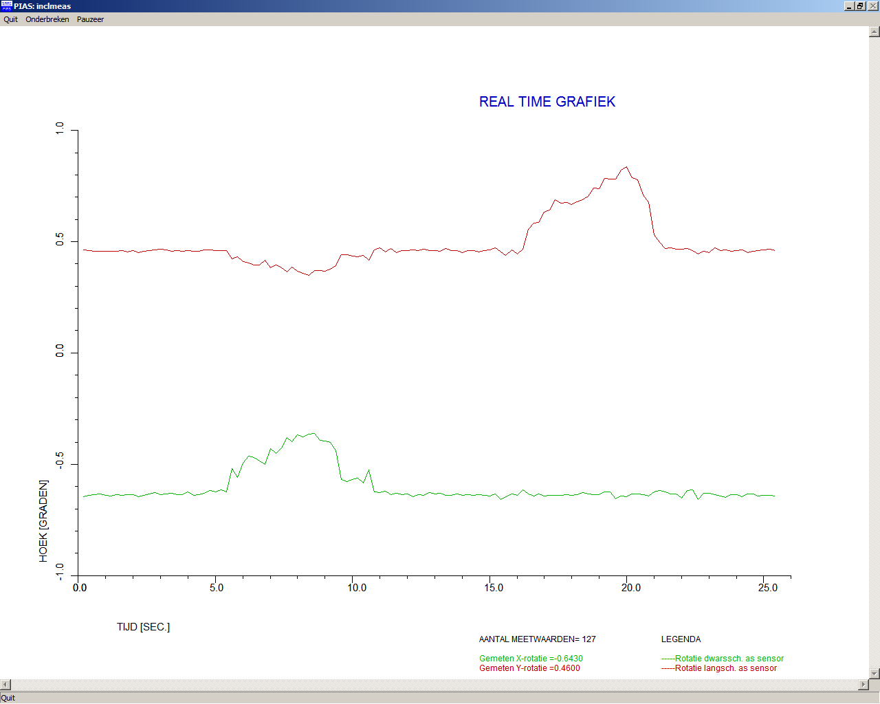
After you have selected this option, the measurement starts immediately. The following is displayed on the screen:

  • Number of measured values. The number of readings until that moment. The measurement frequency is 5 Hz.
  • Measured X-axis rotation. These angles have been determined at the zero measurement relative to a horizontal plane. At subsequent measurements the measured rotations are measured relative to the angles of these axes that have been determined during the zero position or previous inclination measurement.
  • Measured Y-axis rotation. These angles have been determined at the zero measurement relative to a horizontal plane. At subsequent measurements the measured rotations are measured relative to the angles of these axes that have been determined during the zero position or previous inclination measurement.
  • Measured inclination. This inclination is the change in angle relative to the zero position or previous inclination measurements. During the zero measurement (first measurement) this value is not displayed, only the position of the separate X- and Y-axis of the inclination sensor relative to a horizontal plane is determined.
  • Graphic presentation measured X-Y rotation and inclination.

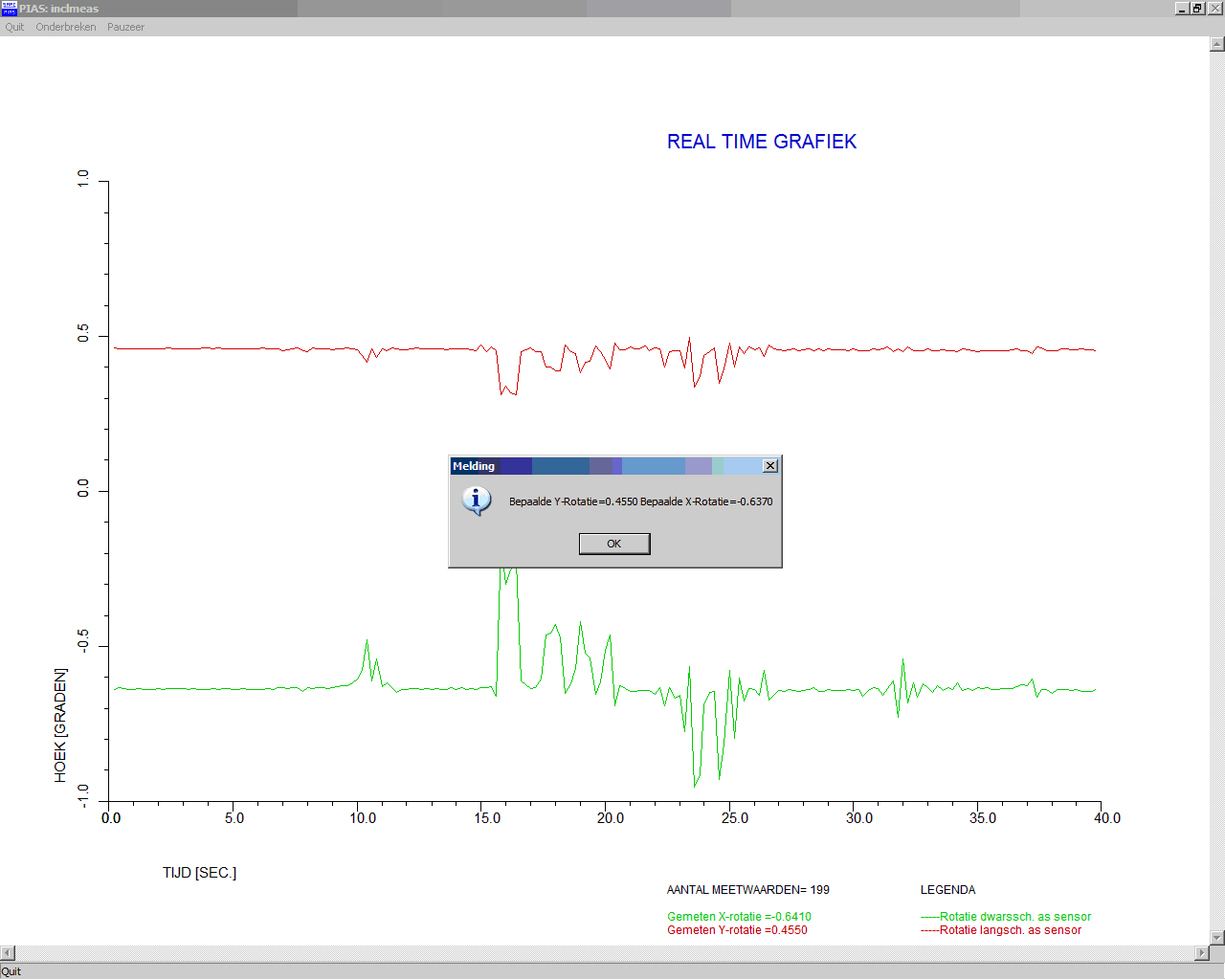
The first image below is a zero measurement, the second one a later measurement (after displacement of inclination weight), where also an inclination is measured and displayed.

inclmeas_test_nul_meting.png
Zero position
inclmeas_test_andere_meting.png
Measurement after relocation

During the measurement one has the following possibilities:

  • One has the measurement finished automatically when the module has determined the correct inclination or the maximum number of measurements has been reached.
  • [Quit]. The measurement is stopped, measured values are not saved.
  • [Interrupt]. After you have selected this option, the following question is asked. The inclination or zero position determined so far is saved. This may result in an incorrectly determined inclination or zero position, because the measurement had not yet been stopped automatically.
  • [Pause].

Last measurement again

After choosing this option the last measurement will be repeated. Earlier determined angles and measurements will be erased.

Remove all saved measurements

All measurement data will be ereased. If a new measurement is started a zero measurement will be done fisrt.

Output of measurements to screen

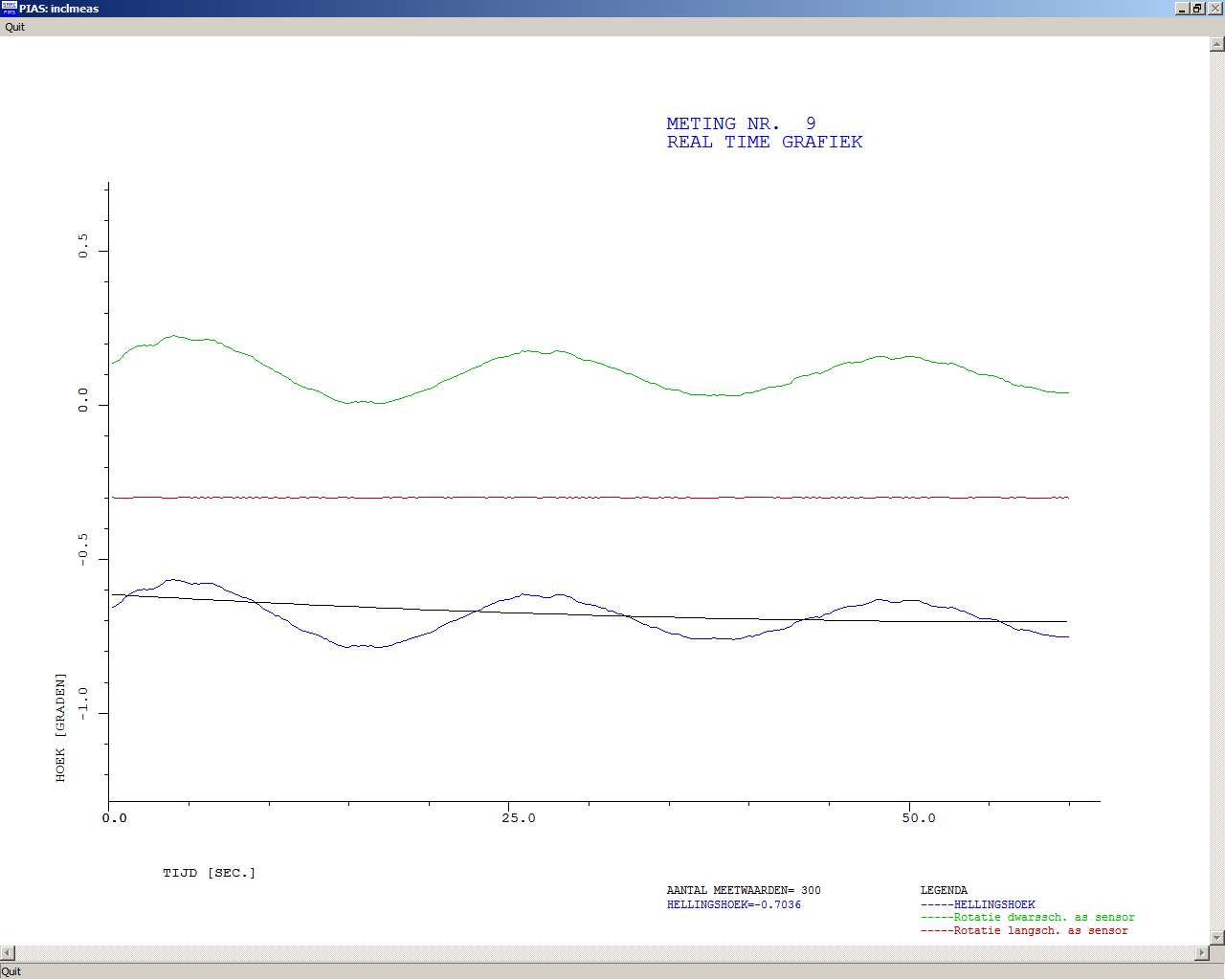
When you choose this option, a menu appears to choose which set of data should be displaced. The data sets are called by the descriptions given in Inclination measurement. After selecting the desired set, the data as given in option Inclination measurement, the determined inclinations and the number of measured inclinations will be presented on screen. With <Enter> you continue to the graphical representation. This is a graph of the data as measured and the function used to determine the correct inclination. The correct inclination is the value of the function completely at the right in the graph. Also the description of the set as given in Inclination measurement is presented.

Output of measurements to printer

All graphical information as presented in the previous option is sent to the printer.

Output of measurements to ASCII file

With this option the measurement data (of all measurements) can be exported to a ASCII file.

Settings of digital inclinometer

There are four settings:

  • Type of sensor
  • Serialport
  • Minimum/maximum number of readings