|
PIAS Manual
2026
Program for the Integral Approach of Shipdesign
|
|
PIAS Manual
2026
Program for the Integral Approach of Shipdesign
|
Shell plating can be defined piece by piece as described in Definition of a shell plate, but for large vessels and simple geometry there is a faster way. This action works by defining the seams and butts where the plates should ajoin, in between which plates can be generated in one batch. The action is started from [Shell]→[Seams and Butts] or using the keys <Alt><S><S>.
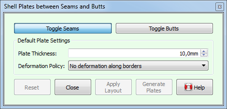
Depending on whether the [Toggle Seams] button or the [Toggle Butts] button is depressed, a click on a polycurve will select it as a seam or butt respectively; a second click will deselect it. Traditionally, where plates ajoin along their longer side are called seams, butts are where plates meet with their shorter side. Fairway however treats seams and butts equally, it does not care what is used. The only difference is that seams and butts are shown in different colors, which may be usitlized for optical clarity.
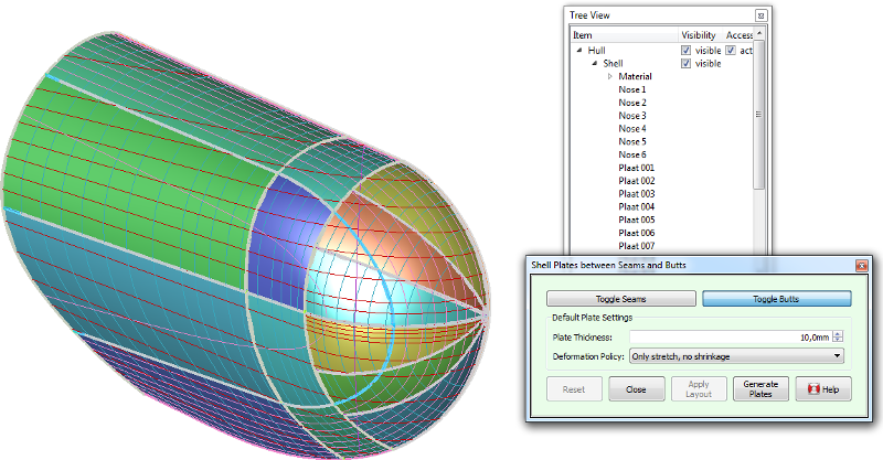
When seams and butts are layed out properly, a click on [Generate Plates] will automatically generate plate regions inbetween the seams and butts in all active solids at once, with a thickness and deformation policy as given in [Default Plate Settings]. These values (as well as the plate color) can be changed individually afterwards using [Definition of a shell plate]. In some cases, a generated plate may not be valid, so it is wise to check whether there are any regions marked invalid in the tree view after plates have been generated. This can happen, for example, when a seam does not end on another seam or butt. Plate expansions and templates can be generated from [Shell plate expansions and templates] in the main menu.
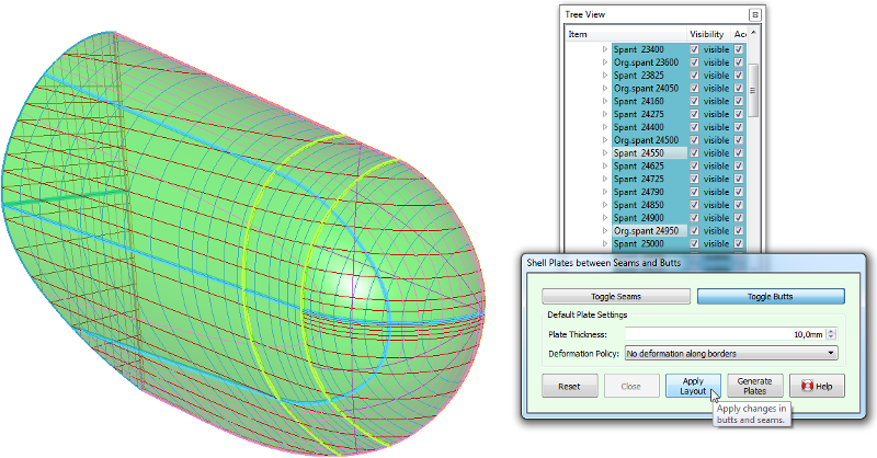
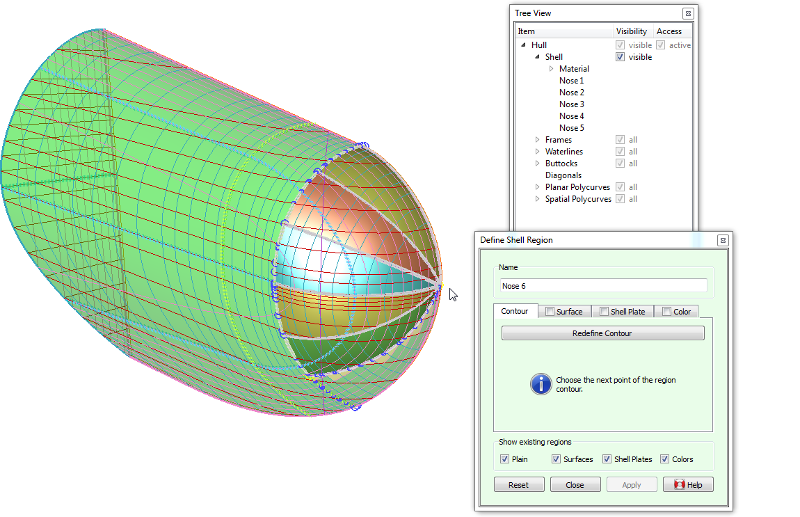
There are two details that are worth noting: Firstly, Fairway takes care not to generate plates where plates already exist. And Secondly, if the time is not yet ripe for the generation of all plates, the layout can be retained until later by pressing [Apply Layout]. This allows for exceptions on the regular layout of seams and butts, using the following workflow illustrated by the sequence of figures below: