|
PIAS Manual
2024
Program for the Integral Approach of Shipdesign
|
|
PIAS Manual
2024
Program for the Integral Approach of Shipdesign
|
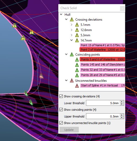
There are several kinds of conditions that can exist in a Fairway model that may be unwanted, although they are allowed and thus no errors. With the menu option [Objects]→[Check Solid] active solids are scanned for the following three conditions:

| Crossing deviations. Fairway allows crossing polycurves to deviate from their common intersection point to a configurable degree, which is a valuable functionality in the process of incremental hull fairing. However, larger deviations can cause deficiencies in surface generation, and a production-ready model should not contain deviations that exceed tight bounds. If the corresponding checkbox is ticked, points are indicated where the distance between intersecting curves exceed the given threshold. The actual distance is shown in the tree view of the docking window, and by expanding an item either of the two corresponding curves can be selected to resolve the deviation using [Change the shape of a curve]. |

| Coinciding points. Points that have identical coordinates or that are unproportionally closely spaced can be confusing, and they can cause complications for fairing and degrade surface rendering. Where possible, one may want to eliminate such coinciding points. By ticking the corresponding checkbox all points that fall within the given threshold are marked. The tree view in the docking window shows the respective curve. |

| Unconnected knuckle points. Usually, one will want corresponding knuckles in successive polycurves to be connected by another polycurve or chine, to express that surface feature across the shell surface. To easily detect any unconnected knuckles, the corresponding checkbox can be ticked. |
To prevent parts of the model from occluding an area of interest, the menu option [Display]→[Clipping]→[Clip to Box] can be used to hide the parts of the model that fall outside a resizable box.
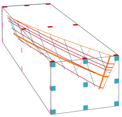
The coloured facelets can be picked and dragged to resize the box (along the edges and in the corners) or to translate the box (in the middle of each face). The box can be resized to contain the whole model with the menu option [Display]→[Clipping]→[Clip Box Contain All]. The option [Display]→[Clipping]→[Hide Box] will hide the box and its facelets, but the clipping will remain active.
When a curve is being manipulated that partly falls outside the clipping box, it will not be clipped but drawn in its entirity.
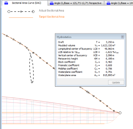
The menu option [Hydrostatics]→[Hydrostatic Data] will bring up a window with hydrostatic information of the vessel. The window can either be floating separated from the main window, or be embedded in it somewhere around the modelling area. The hydrostatics are dependant on the frame shapes, so when a frame shape changes, the [Update] button in the hydrostatics window will be enabled, which allows the information to be recalculated.