With this module the ship motions in natural seaways can be estimated in the frequency domain, using one of the following methods:
- Jensen, an emperical method, meant for quick estimations in the design phase. An advantage of this method is that the calculations are based on the global hull form coefficients, so no hull form is required yet.
- A strip theory based method which performs calculations using the hullform as defined in PIAS.
Overview and applicability of the estimation methods
It is important to note that this manual will only discuss the PIAS implementation of the methods. The user is assumed to have knowledge of seakeeping and wave theory, as can be found in standard text books and is taught in universities.
Jensen
- Note
- Please take the warning in the note of Overview and applicability of the calculation methods. — on the attitude with respect to empirical/statistical estimation methods — at heart.
This method is based on Jensen, J.J., Mansour, A. & Olsen, A.S. (2004). Estimation of ship motions using closed-form expressions. Ocean Engineering, 31(1), 61–85. They developed closed-form semi-analytical expressions for the response function for heave, pitch and roll and the vertical motion, velocity and acceleration of monohull ships.
In the paper it is stated that its formulae estimate the motions fairly accurate, with the exceptions of:
- The heave motion is too small for wavelengths larger than the ship length.
- The pitch motions is too large where the wave length is around the same as the ship length for Froude numbers larger than 0.2.
- The roll motion is too large around the resonance frequency.
Strip theory
A strip theory method has been implemented based on Bertram, V., Veelo, B., Söding, H., Graf, K. (2006, May). Development of a freely available strip method for seakeeping. In COMPIT (Vol. 6, pp. 356–368). The program PDstrip which is presented in this paper is used as the computational engine in Motions. In order to use the strip theory method a hullform is necessary. Motions uses the PIAS frame model that is described in Hull form representations. The program is currently only suitable for monohull vessels, while added hullforms will not be taken into account. The current implementation of the program mirrors starboard and portside parts of the hullform in order to speed up the calculations, and thus is only suited for symmetrical hullforms. For common hullforms 30 to 40 frames are considered sufficient to properly capture the hullform. Although the program can handle the PIAS maximum number of frames (currently 500), and accounts for double frames. Gaps in a frame are accepted, provided that the frame does not intersect itself. An example of what is not allowed and what is allowed is shown in the image below.

Example of a gap in a frame. On the left the frame intersects itself, which Motions does not accept. On the right is an example of a gap that does work in Motions.
Only the underwater part of the hull is used in calculations, which is ‘cut off’ from the hullform at the user-defined draft and trim. When multiple intersections with the waterline are present in a frame, as may be the case in a propeller tunnel which is not wholly submerged, the part of the frame that is present after the first intersection of the frame shape with the waterline is neglected.
Wave spectra
In order to estimate the probability of exceedance of a motion, a wave spectrum is required. Six wave spectra have been pre-programmed, according to the equations in Stansberg, C.T., Contento, G., Hong, S. W., Irani, M., Ishida, S., Mercier, R., & Kriebel, D. (2002). The specialist committee on waves final report and recommendations to the 23rd ITTC. Proceedings of the 23rd ITTC, 2, 505–551. These spectra are discussed below.
- Note
- The quasi-static wave as specified with config, see Wave amplitude, has no influence on the ship motions computations of this module. After all, in Motions the calculation is not based on a single static wave, but on a distribution (a spectrum) of many waves.
Jonswap
The JONSWAP spectrum defines seas with finite fetch. It requires input of a peak frequency and a peak enhancement factor. The approximations for this spectrum are believed to be correct for a range of the peak enhancement factor between 1 and 7. When the wind speed U and the fetch F are known, the peak frequency of the spectrum can be calculated according to \(f_p=\frac{g\hat{F}^{-1/3}}{U}\) where \(\hat{F}=\frac{gF}{U^2}\).
Spectra of the generalized Pierson Moskowitz form
The other spectra are of the generalized Pierson Moskowitz or Bretschneider form. These spectra define fully developed seas. The spectra and their required input are listed below:
- One-parameter Pierson-Moskowitz: requires input of either wind speed, peak frequency or significant wave height. When one of these values is inputted into the program, the corresponding values for the other two parameters are automatically updated.
- Two-parameter Pierson-Moskowitz: requires input of the peak frequency and the significant wave height.
- ISSC: requires input of the mean frequency and the significant wave height.
- ITTC: requires input of significant wave height and one of the energy, peak, mean or zero-crossing periods.
- Liu: requires input of the wind speed and the fetch.
Main menu
Input data for ship motion analysis
In this window the parameters which are needed for the various methods are given. The list below now only lists those for the Jensen method. For additional detail it is advised to consult the source publication.
- Method: the chosen calculation method.
- Name of the vessel: can be taken from the PIAS hullform if a project name is defined in Main dimensions and allowance for shell and appendages.
- Start frequency, frequency interval and end frequency: the frequency range for which the motions are calculated is defined here. Should the frequency interval be zero or larger than (end frequency – starting frequency), the calculation shall only be performed for the starting and end frequency.
- Draft: when derived from a hullform the design draft as defined in Hulldef is used.
- Trim: according to the definition in Definitions and units.
- Water depth: distance from the surface of the water to the bottom.
- Main hullform parameters: length waterline, breadth, draft, block coefficient, waterline coefficient: if a PIAS hullform is available, these parameters can be derived from it.
- Calculate roll RAO: choice to calculate roll with the Jensen method. Can be turned off if the required additional input of the waterplane coefficient, metacentric height or the natural roll period is not available. The length ratio is chosen and the critical damping is optional.
- Metacentric height (GM): is linked to the VCG.
- VCG: height of the vertical center of gravity (is linked to the metacentric height).
- Natural roll period: if the natural period is not known it can be estimated. For this the IMO Intact Stability Code 2008 A.2.3.4 is used, which uses the length, breadth, draft and metacentric height parameters as input.
- Length ratio: the Jensen method simplifies the vessel into two prismatic beams for the roll calculation, with the same draft but different breadth and cross-sectional areas. The length ratio δ defines the length of these two prismatic beams, as seen in figure below. The value of the length ratio must be between 0 and 1, but not greater than the waterline coefficient.
Length ratio delta (Jensen, Mansour & Oslen, 2004)
- Critical damping: With the Jensen method the viscous roll damping is approximately accounted for by adding a percentage of critical damping to the estimated inviscid damping. It is inputted as a percentage.
- Wave spectrum: select one of the wave spectra mentioned in Wave spectra.
- Number of speeds: a maximum of 50 can be given.
- Number of wave headings: a maximum of 100 can be given. A wave heading of 0 degrees means following waves, a wave heading of 90 degrees beam waves from portside, and a wave heading of 180 degrees signifies head waves.
- Radius of gyration kxx: the radius of gyration about the longtitudinal axis through the centre of gravity. An estimation method based on IMO Intact Stability Code 2008 A.2.3.4 is available. For a more accurate estimation we recommend Grin, R., Ruano, F.S., Bradbeer, N., Koelman, H., On the prediction of weight distribution and its effect on seakeeping, Proceedings of PRADS 2016, 4–8 September, 2016, Copenhagen, Denmark. pp. 227–235, which is available on the SARC website..
- Radii of gyration kyy and kzz: the radii of gyration about respectively the transverse and vertical axes through the centre of gravity. Estimations are available, based on the common estimation formula \(k_{yy} = k_{zz} = 0.25*L_{pp}\). For a more accurate estimation we refer to the paper mentioned above.
- Radii of gyration kyx, kyz and kxz: the radii belonging to the combinational products of inertia longitudinal-transverse, transverse-vertical and longitudinal-vertical respectively.
- Damping ratio: the ratio between the actual and critical damping of the free roll motion of the vessel. Also known as ‘the damping coefficient’. The implementation is based on el Moctar, B.O., Schellin, T.E. & Söding, H. (2021). Numerical Methods for Seakeeping Problems, Springer International Publishing. The damping ratio is used to add viscous damping to the calculations of the strip theory method. After all, the strip theory is based on the potential flow theory, which does include damping, although not the so-called viscous damping (which is the effect of fluid friction). When applying the ‘bare’ strip theory, this may cause the real damping to be underestimated, notably for the roll motion. It is possible to measure the damping ratio, which is one of the reasons that this method has been implemented. If this parameter cannot be measured it can be estimated instead, for example with the formula from ITTC procedure for numerical estimation of roll damping. As an illustration, the figure below shows the measured rolldamping of a 14000 TEU container vessel (from Moctar, O.E., Shigunov, V. &Zorn, T. (2012). Duisburg Test Case: Post-panamax container ship for benchmarking. Ship Technology Research, 59(3), 50–64.. Please notice that the values in the graph are in percent, while the input in Motions is in ratio (e.g. 1% is a ratio of 0.01).
Damping ratio of Duisburg Test Case.
Specify output
In these menus the points of interest and the specific output can be specified. The points of interest are the points for which specifc output can be defined in the program, such as the vertical accelerations and the probability that a defined threshold value is exceeded in the defined wave spectrum. The choice has been made to separate the definition of the points and the definition of the output, so that it is easier to define multiple outputs for a single point. In this way it is comparatively easy to define multiple threshold values for a single point, while it is also possible to specify the output of displacements and accelerations for that point.
One specific point of interest that is always defined is the center of gravity.
- For the strip theory method the location of the the center of gravity is derived from the hullform and the input parameters.
- For Jensen the longitudinal coordinate of the center of gravity is half the waterline length, as specified by the method.
Specify points of interest
In this menu the so-called ‘point of interest’ can be defined. A point is defined by a name, abbreviation and location coordinates. For the limited Jensen method, this location is only defined by a longitudinal position, the transverse position is always on the centerline and the vertical position is always on the waterline. For the strip theory based method all three coordinates are required.
Specify output at point of interest
In this menu the output for a point of interest is specified. First, after a new line has been created, a point of interest can be selected from a popup menu containing all of the points of interest defined in the previous menu. Alternatively, in the second column an abbreviation of one of the points of interest can be manually entered.
The column ‘output type’ opens a menu to select all the output for the point of interest. The selected (relative) displacements, velocities and accelerations are calculated on the specified location of selected point of interest. As only three of the six motion transfer function can be calculated using the Jensen method, and information about the phase angles of these motions are not calculated, only vertical motions on the centerline of the vessel can be calculated. A more complete calculation, where also the transverse and longitudinal motions, velocities and accelerations are calculated will be introduced with the strip theory method.
If a wave spectrum is defined in menu Wave spectra, and only a single type of output has been selected, then a probability of exceedance of a defined threshold value of the output type against the wave spectrum can be calculated. When this option is selected, a threshold value must be defined. An acceptable probability of exceedance can optionally be defined, which is used to clarify the graph output. The unit of the threshold value naturally depends on the selected type of output, and is shown in the cell comment when the cell is selected. The acceptable probability is given in percentages (0%-100%).
Specify output options
In this menu the printing of the RAO tables can be enabled or disabled.
Calculate and print output
Using the parameters given in the first menu option, the output specified in the second menu option is calculated and printed as specified. A complete output contains:
- For each speed and wave heading an output table as specified in Specify points of interest. If the option to calculate probabilities of exceedance has been enabled these are also printed in a table and plotted in a polair diagram.
- For each speed and wave heading the RAO tables if these have been enabled in Specify output options.
- An overview of the input that has been used to perform the calculations.
Example of an output table of calculated displacements
Example of a response spectrum output table
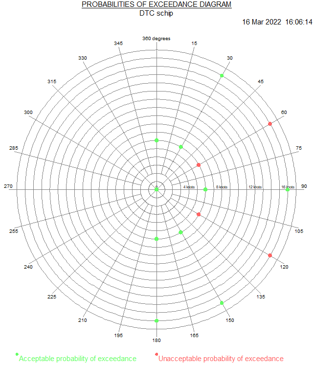
Example of an polar diagram of the acceptability of probabilities of exceedance
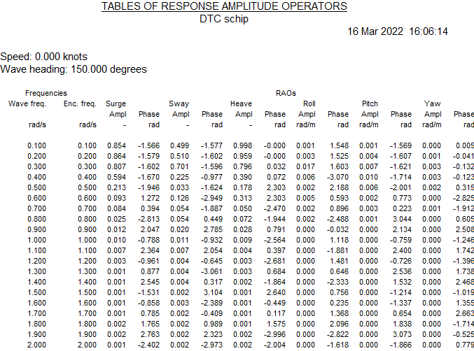
Example of a RAO output table
Filemanagement
With this option design versions can be managed, with a mechanism as described in Data storage and backups.