|
LOCOPIAS Manual Seagoing Vessels
2026
Loading Computer Software
|
|
LOCOPIAS Manual Seagoing Vessels
2026
Loading Computer Software
|
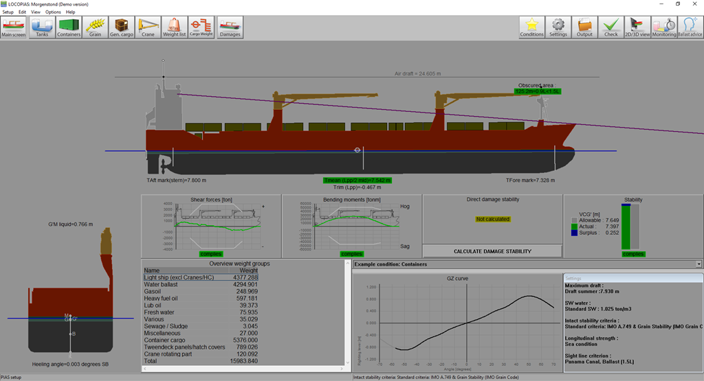
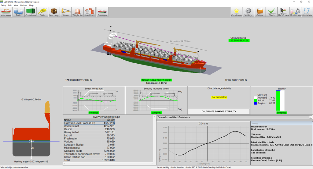
At start-up LOCOPIAS opens with the main window, this is the central point in the software. From here, the loading condition can be defined, applicable criteria and settings can be chosen and calculations can be invoked.
A typical example layout of the main window is shown below, with an explanation of the labeled elements right below that.
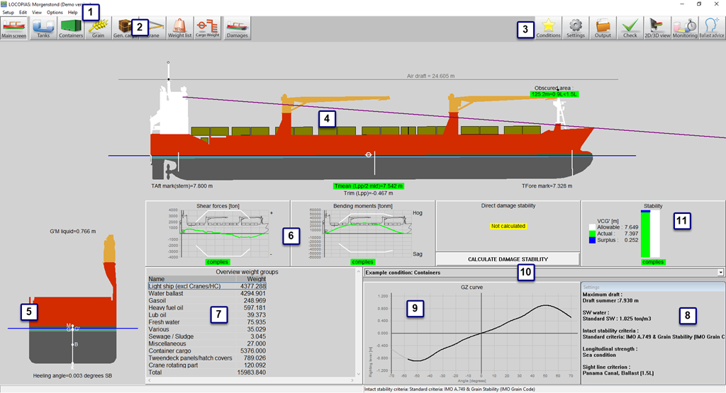
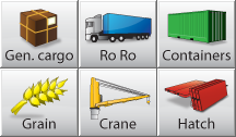
These tool bar buttons provide quick access to the main window and available cargo modules to load specific types of cargo.
The menu bar at the top of the main window (item 1) gives access to the following functions:
Weight items can be grouped in so-called weight groups, were a weight group is a category of a particular content, such as ‘diesel oil’ or ‘fresh water’. The weight groups are managed from this location in the program. The user can add, modify and delete weight groups themselves. When deleting a group, a check is made to see if there are still weight items of that group, and if there are, a notification is given and it is better not to delete the group. There are some default weight groups that are fixed in the program and cannot be changed or deleted. Editable properties are:
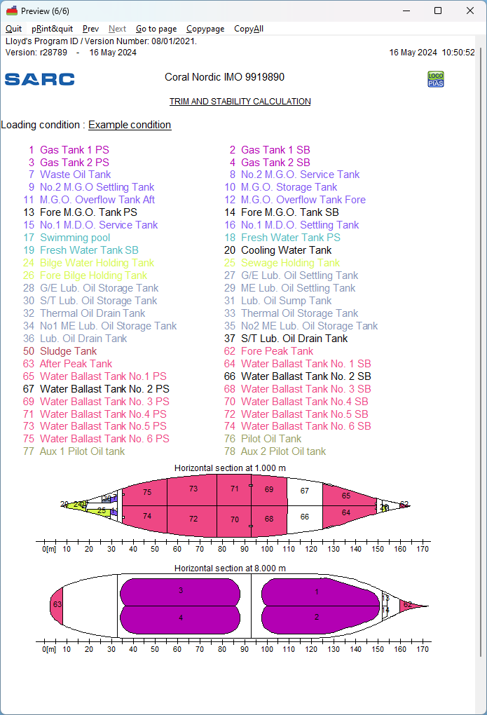
Go to this menu to add or edit cross sections and views of the tanks. These sections and views are automatically added to the output of intact stability calculations.
See 2D/3D View
In general, you can use the following steps to define a loading condition and perform the required calculations. Please note that this workflow is just one way to get you started, it is not the only possible way to use LOCOPIAS. All actions can be performed in random order and frequency but it is important to check the compliance with all the appropriate criteria after a change in the loading condition has been made The functionalities will be elaborated further in the remainder of this chapter. This example starts at the main window.

| Select the [Conditions] button and create a new condition. When LOCOPIAS is opened for the first time, the main window shows a preprogrammed example condition. By creating a new condition, you start with a preprogrammed default condition. |

| Click the [Settings] button and adjust the settings according to your situation. By adjusting the settings to the current situation before loading your cargo, useful feedback can be received during configuration of the loading condition. Settings are applicable for the current loading condition. |
| Go to the [Tanks] module to modify the contents of consumables e.g. fresh water, fuel oil, lubricating oil. | |
In the [Weight list], miscellaneous supplies, e.g. crew, provisions and stores can be entered. | |
| Select the appropriate modules for your cargo type and define your cargo. |
| Open the [Tanks] module again. When all cargo is loaded, the floating position can be optimized by adding water ballast. | |

| The [Check] button provides a quick check of stability and strength at any moment during this process. |

| Press [Output] to perform calculations and generate output on screen or on paper. |

| Press [2D/3D view] to view a three-dimensional representation of your vessel, if available. |

| Press [Monitoring] or [Update Monitoring] to switch on the monitoring functions in LOCOPIAS, if available. |
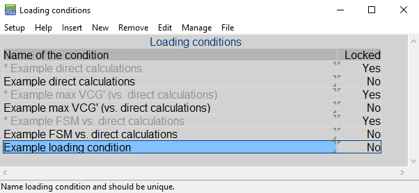
By pressing the [Conditions]-button, the loading conditions menu, as shown in the figure below, will appear. In this window the defined loading conditions are displayed and can be managed. You can create a new loading condition and you can delete, rename, copy/paste or export existing conditions. To modify a loading condition, select a condition and double click on it or press the <enter> key. The main window will now reflect this loading condition.
The new condition is a preprogrammed default condition.
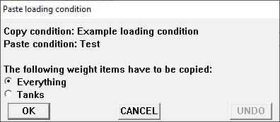
Copy a loading condition and paste it over another loading condition to create a loading condition that has the same properties. If a specific module has been purchased you can choose to paste the complete condition or just the cargo defined with the specific module. The newly pasted condition will appear on the main window, as shown in the figure below.
All settings that apply to the loading condition can be altered in the settings menu. By clicking the [Settings]-button, the following menu, as shown in the figure below, opens. It has several tabs which can be selected. These tabs are explained below.
(Re)configures the vessel. See “Ship-specific data and test conditions” booklet for more information about the possible configurations.
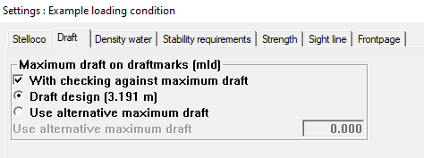
Select the applicable maximum and minimum drafts. If the option [use alternative maximum draft] is selected, a user-defined draft can be entered. The selected drafts will be displayed in the summary of the loading condition, with the conclusions for the applicable stability criteria.
The density (specific weight) can be set and will be stored per loading condition. This density is then used for all calculations performed with the loading condition.
Different intact stability requirements can be available for the vessel depending on the operational sailing area.
Different values of maximum allowable bending moments and shear forces can be applicable for a vessel at sea or in a harbour. If these values are available, the appropriate values can be selected here. The selected values are also indicated in the output of longitudinal strength.
This option makes it possible to indicate whether, in addition to the normal stability output, a polar diagram should be printed which shows the maximum permissible anchor chain angle at each anchor chain angle. Anchor force still permitted according to the anchor-handling stability requirements. For this purpose it is no need to assess the loading condition against other than the standard stability criteria.
Depending on the regulations under which the vessel will sail, the line of sight requirements can be adjusted here.
<dt>Trimoptimalisatie</dt> <dd>If the module \ref loading_module_trim_optimization is active, the speed and delta displacement can be set here per loading condition.</dd> <dt>Frontpage</dt> <dd>It is possible to add a front page to your output. You can select the text lines to be printed and enter free text as desired (e.g. a voyage number, port of loading, etc.). </dd>
This button is only available if a 3D model of the vessel is available. It toggles between side view and three dimensional view of the hull and cargo. By choosing the menu [View]→[3D View] it is possible to edit materials, colors, and light effects of the 3D representation. The 3D image can be saved to file or sent to a printer.
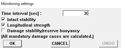
This option is only available when purchased and a connection with a tank gauge system is available. After selecting the icon for [Monitoring] a settings popup-window, as seen below, will appear. Here you can enter the time interval which will be used for reading the tank data, calculating the intact stability, longitudinal strength and damage stability (which is available and selected) and updating all data in the main screen. As long as the monitoring mode is active, it is not possible to edit loading conditions. This mode can be stopped by selecting the icon for monitoring again.
This function is only available if 'direct monitoring' is delivered with LOCOPIAS. 'Direct monitoring' is an additional feature of LOCOPIAS that can be configured to continuously send calculation results to other software, via a suitable interface. These results may include including tank fillings, weight items, results of (damage) stability and longitudinal strength, etc.
With this function the actual loading condition can be exported to update the loading condition as used in a second instance of LOCOPIAS, running in 'direct monitoring' mode. That instance LOCOPIAS will read the updated loading condition and recalculate results. Thus, monitoring need not be interrupted to define changes cargo, bunkers, or other weights on board or calculation settings.
Details of the configuration of 'direct monitoring' and the interface used are described in the ship-specific documentation.
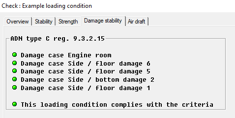
Click the [Check]-button to check that the loading condition complies with the (damage) stability and strength requirements. After clicking the [Check]-button, a window opens with several tabs: overview, stability, strength and damage stability, if applicable. Compliance with the requirement is indicated by the color of the bullet (complies = green, does not comply = red). If, for instance, the overview shows a red bullet under intact stability, the corresponding tab provides more information as to the reason for non-compliance. Note that when the vessel operates under more than one classification society, the set of damage stability criteria applicable to the loading condition can be set via the menu bar item [Options]→[Select stability criteria]. The intact stability criteria can be set per loading condition via Settings.
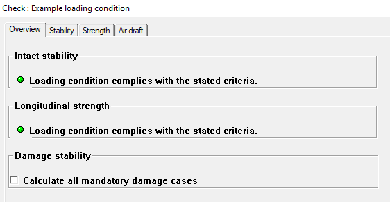
When you want to check all mandatory damage cases (type-3) select: ‘Calculate all mandatory damage cases’ and press OK. Now the Check window has generated a new tab called Damage stability. Here you can check whether the damage cases complies with the criteria (complies = green, does not comply = red).
User defined damage cases (type 4) have to be calculated via Output.
If more detailed information is desired, for intact stability, damaged stability (type 3 and/ or type 4) or strength calculations, one should create a full listing via Output. When ‘Preview/Clipboard’ is selected (see Preview of output to screen, and export of computation results) this output is printed on screen. We recommend to make use of ‘preview/ clipboard’. Printing the results shown on screen can be done with by clicking ‘Output’ and then select the full listing one wants to be printed (on screen or on paper) and the full listing will be printed.
The procedure for calculating damage stability is described in: Damages.
You can use ‘Output’ to perform full calculations and to make a printout. If the selected printer is ‘preview/clipboard’ the output will appear on screen. To get the output in a preview on screen, see Preview of output to screen, and export of computation results.
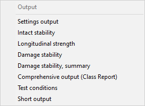
The following output options can be available in your version of LOCOPIAS:
Select which data is to be printed in the full output. See Output Settings.
Standard format output of intact stability calculations with an overall conclusion for compliance with applicable stability requirements.
Output of longitudinal strength calculations with an overall conclusion for compliance with selected allowable bending moment and shear force requirements.
Output of torsional moments calculations with an overall conclusion for compliance with defined maximum allowable torsion moments.
Full output of damage stability calculations of the mandatory (type 3) damage cases with an overall conclusion for compliance with applicable stability requirements.
Output of damage stability conclusions of the mandatory (type 3) damage cases.
Full output of damage stability calculations of the selected damage cases with an overall conclusion for compliance with applicable stability requirements.
Output of damage stability conclusions of the selected damage cases.
Output of the standard format of all available calculations (including mandatory damage cases, if applicable) with a common conclusion in accordance with the requirements. This ‘Class report’ should be printed to see if full compliance with all required criteria of the vessel is met. A hardcopy or digital copy should be saved for future reference. This ‘Class report’ should be printed with all the available and relevant output settings.”
Output of (damage)stability and/or longitudinal strength of the test conditions calculations. The output of the test conditions can be compared with the condition in the approved/ stamped “Ship-specific data and test conditions” booklet of the ship. The output of the test conditions should be regularly verified with this bookletto ensure that the loading instrument is functioning correctly. If the output of a test condition does not correspond to the values in the “Ship-specific data and test conditions” the results of calculations cannot be trusted. Re-installation of the software might be necessary. If that doesn’t solve the problem, contact SARC
A summary of the loading condition and a conclusion.
Output for all measuring devices, for every tank, in the loading condition.
An overview of all onboard cargoes, including their weight, temperature effect, sounding and etc.. In this list only those tanks are included of which ‘Include this tank in ullage report’ is switched on.
The stowage plan can be shown on screen or printed to paper. All cargoes from all available modules, except grain and bulk, are printed.
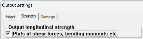
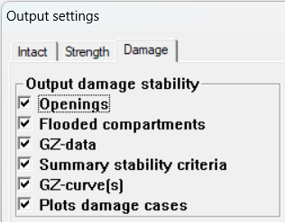
In ‘Output Settings, one can select which data is printed in the full output. The output settings can be made for ‘intact stability’, ‘strength’ and/or ‘damage stability’ whatever is applicable for the type of vessel. For a full rapport, validating the compliance with the applicable criteria one should include all output, except for the ‘frontpage’ in intact stability. 'Frontpage' allows the user to print additional data such as information about the cargo etc. This additional information can be given at Settings.. Not all ships will have a margin line defined and in such cases this could be left out.
Examples of the output can be found in Examples of output.
Available settings:
Intact stability
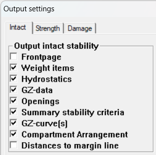
If one wants to include a frontpage, the content of this frontpage can be given at Settings.. Distances to margin line will not be applicable to all vessels.
Strength
Damage stability
Below, examples of output for: Intact Stability, Longitudinal strength, Damage stability, Damage stability (summary) and Damage stability (summary DNV)
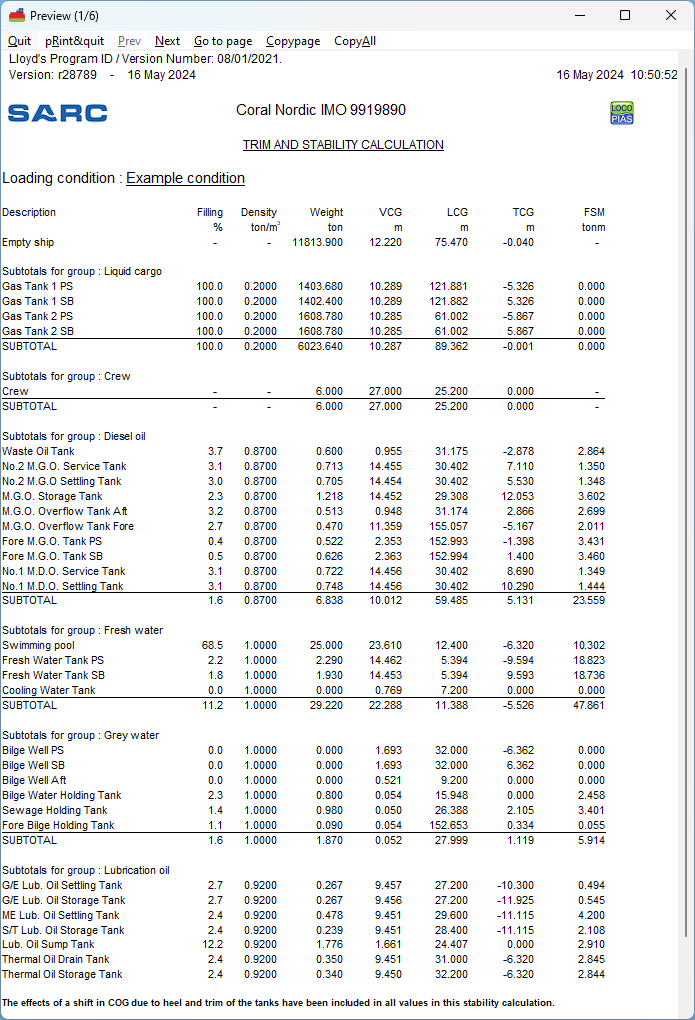
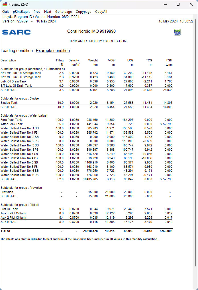
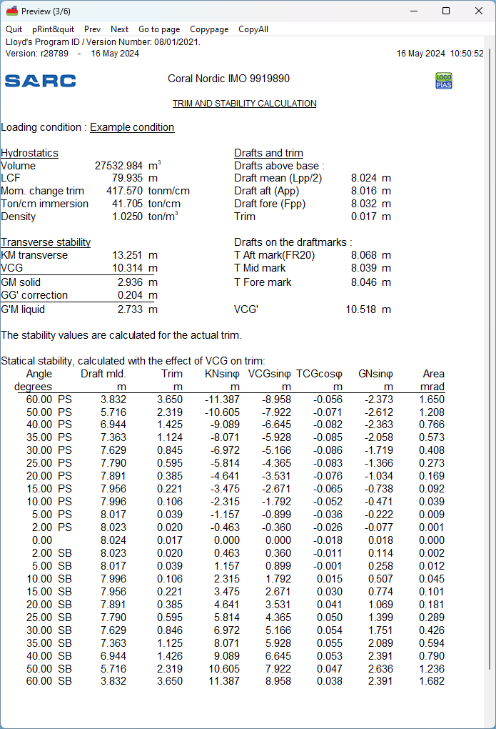
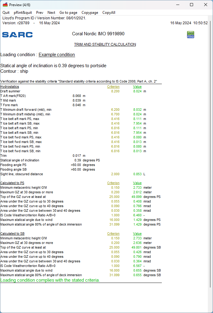
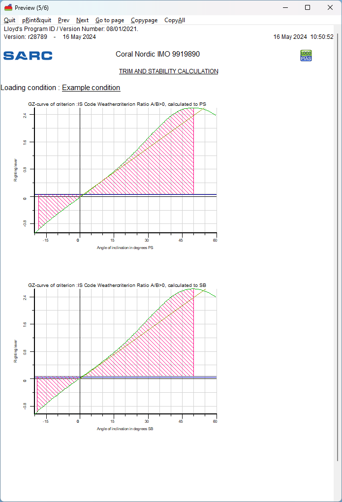
Example of print-out of intact stability. Actual output and/ or results may differ according the choosen calculation, and/ or output settings.
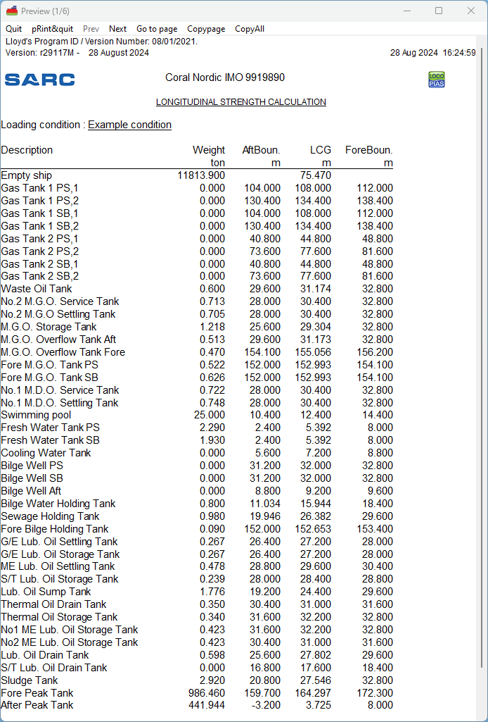
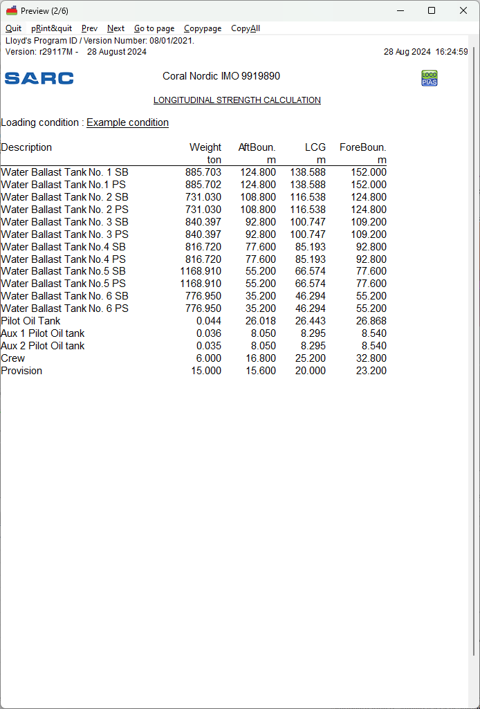
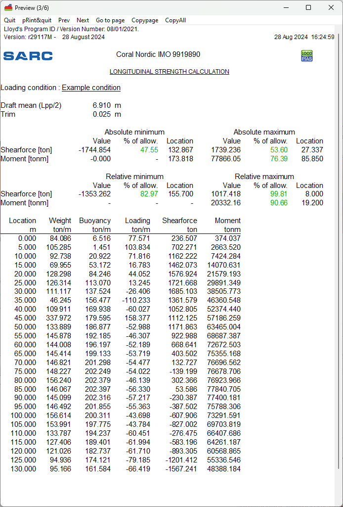
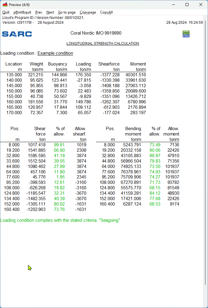
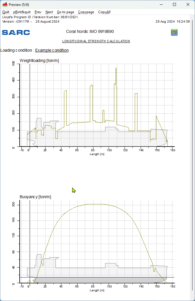
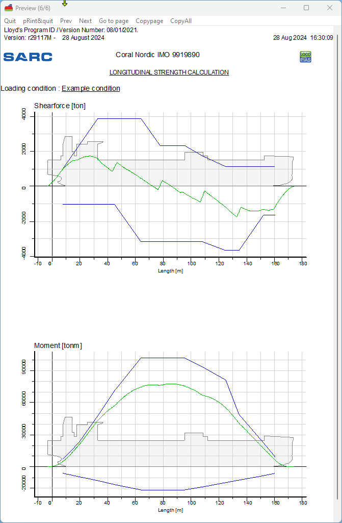
Example of print-out of longitudinal strength. Actual output and/ or results may differ according the choosen calculation, and/ or output settings.
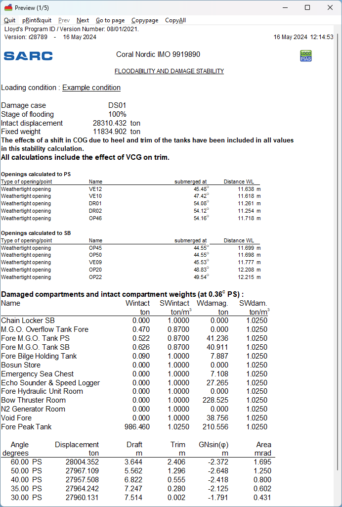
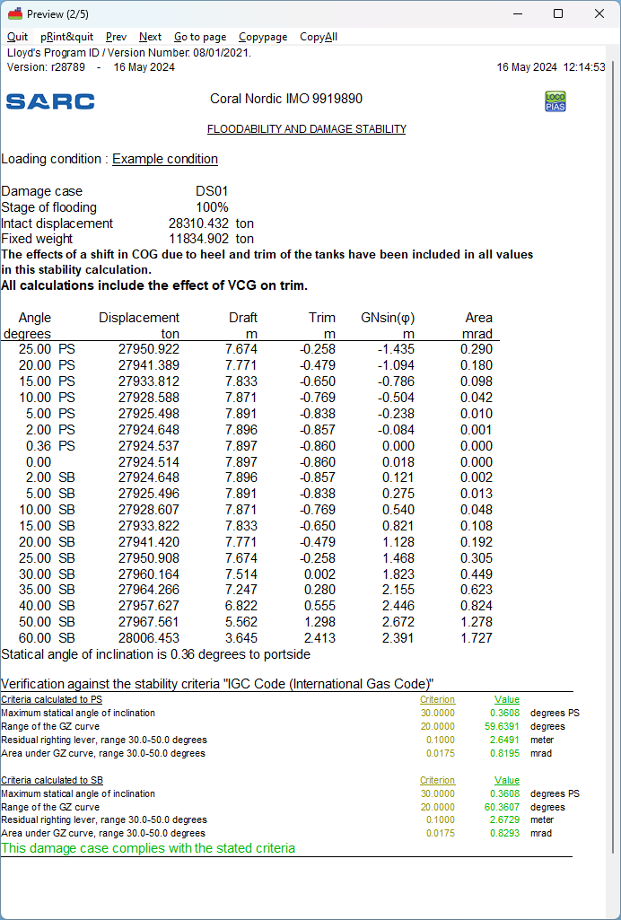
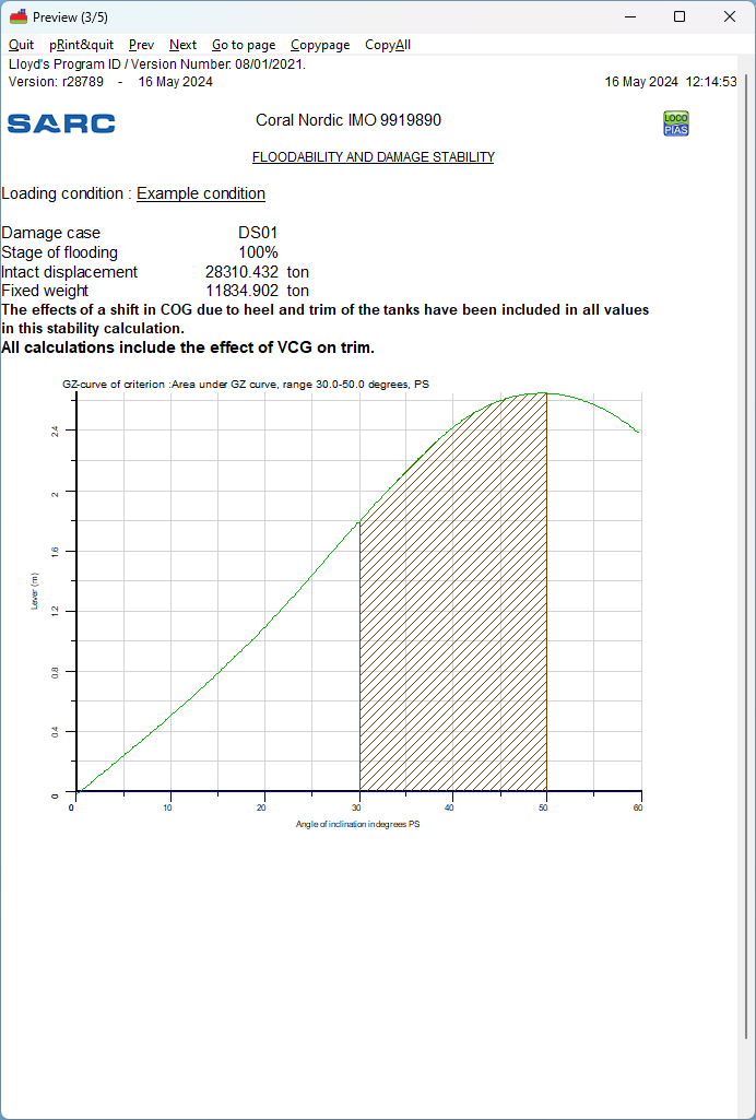
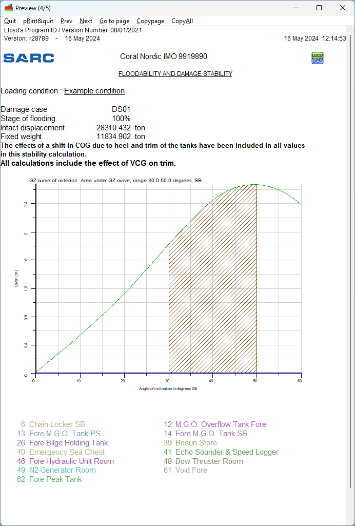
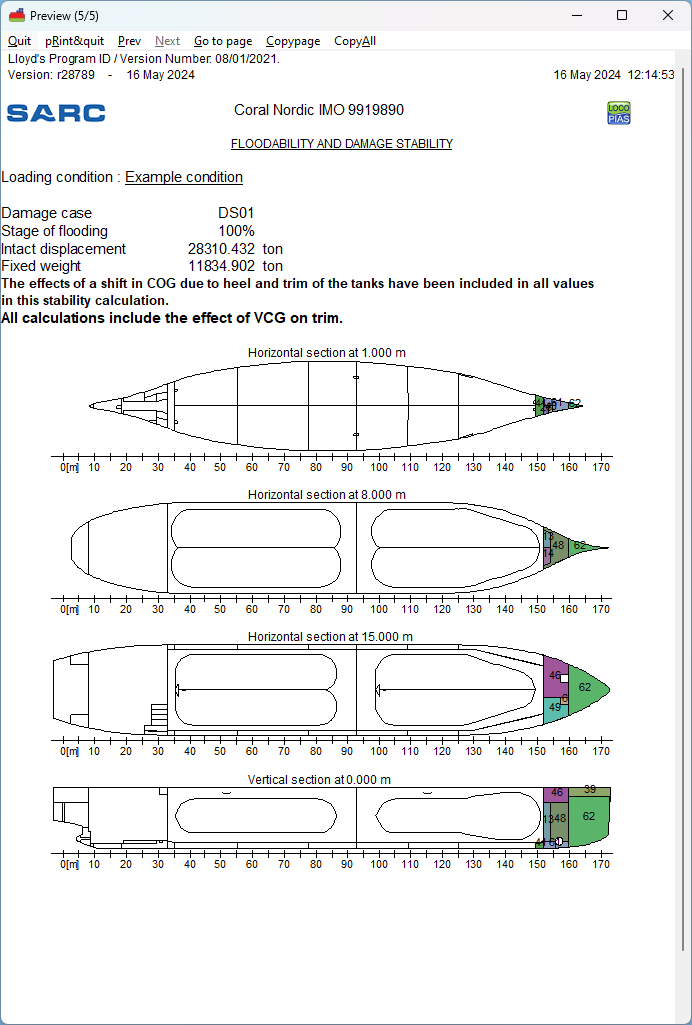
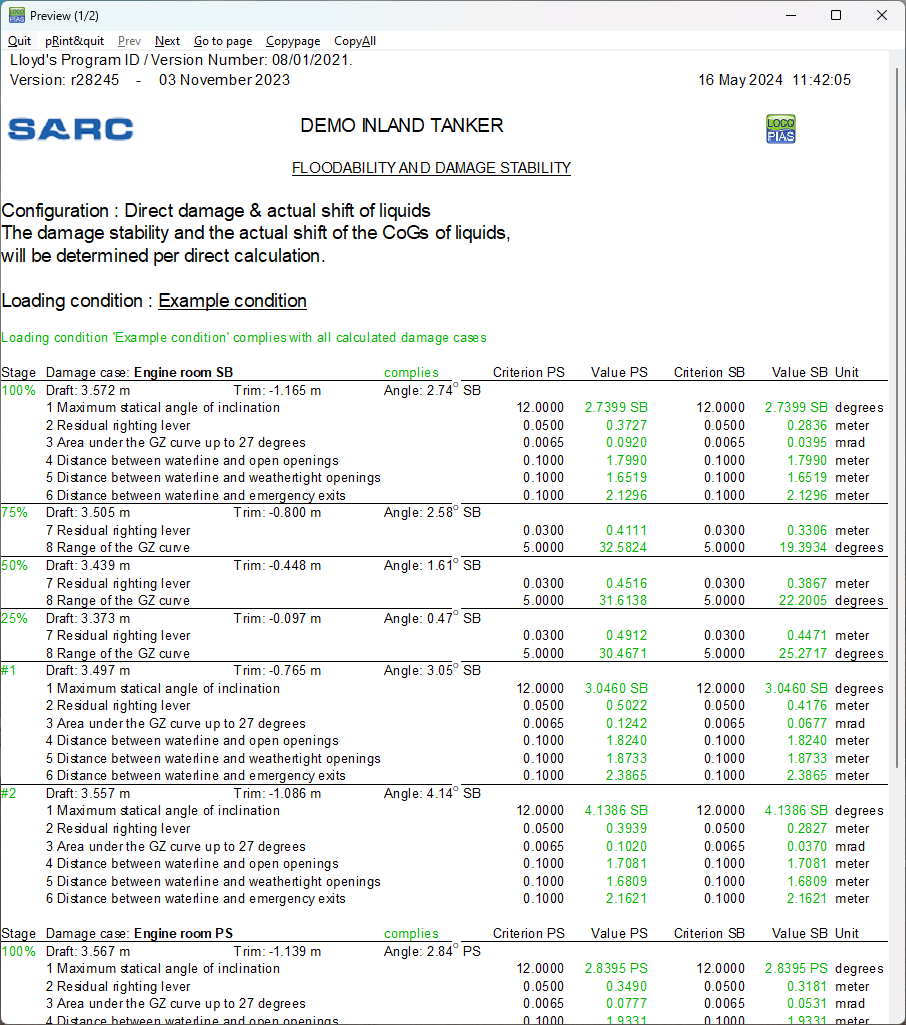
Example of print-out of damage stability. Actual output and/ or results may differ according the choosen calculation, and/ or output settings.
Example of print-out of summarized damage stability. Actual output and/ or results may differ according the choosen calculation, and/ or output settings.
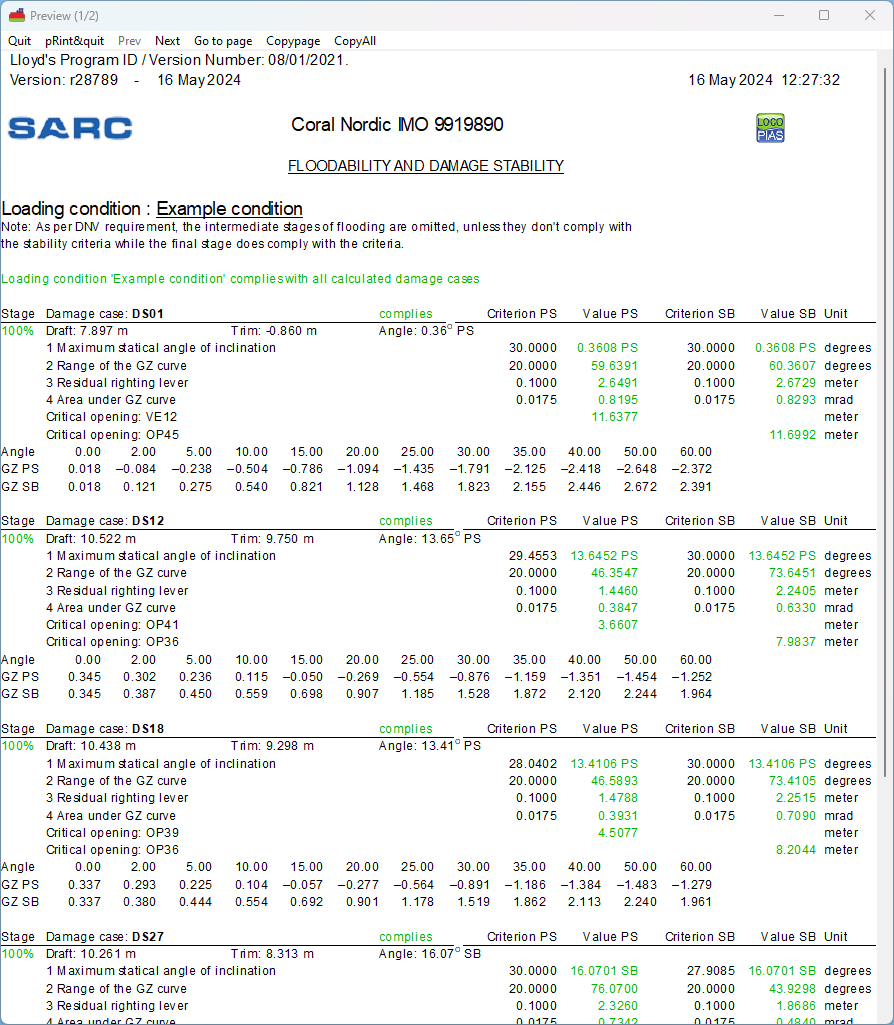
Example of print-out of summarized damage stability according the format of Det Norske Veritas (DNV). As per DNV requirement, the intermediate stages of flooding are omitted, unless they don't comply with the stability criteria while the final stage does comply with the criteria. Actual output and/ or results may differ according the choosen calculation, and/ or output settings.