|
PIAS Manual
2026
Program for the Integral Approach of Shipdesign
|
|
PIAS Manual
2026
Program for the Integral Approach of Shipdesign
|
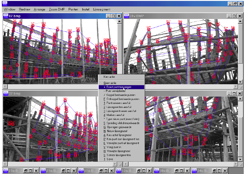
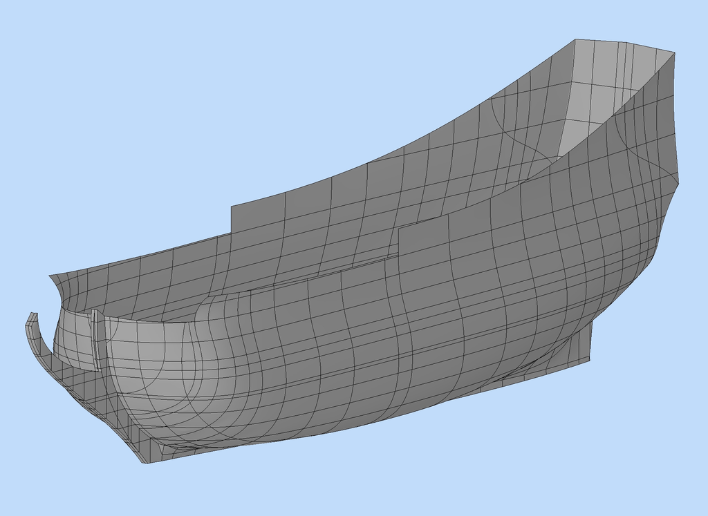
The goal of reverse engineering is to obtain an unambiguous 3D model of the hull shape. The role Photoship plays in this process consists of the construction of a wireframe model, which consists of measured points and user-defined line segments between those points. A solid model based upon such a wireframe can be generated with Fairway (see Convert Wireframe to Solid). Also all other Fairway facilities can be applied on a photogrammetrically measured hull shape, notably post-processing of the hull lines ( Wireframes) and export of the 3D hull model.
The principle of photogrammetry is based on stereovision. The 3D coordinates of measuring points are calculated on basis of the depictions of these measuring points on multiple photos. A comparison with human vision can be made here. In order to see depth, two eyes are necessary. The principle of stereovision is illustrated in the picture below:
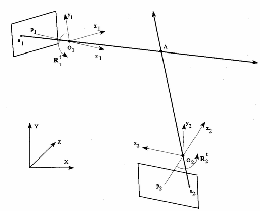
What we see here are the depictions a1 and a2 of point A on two different photos. From a1 and a2 two lines of sight are drawn through the foci O1 and O2. The point of intersection of these two lines of sight defines the 3D coordinates of A. This principle is named `intersection'. For this principle to work, the orientation of each photo has to be known. These are calculated with the aid of reference points. Reference points are measuring points with known coordinates. They are also being used to give the model the right scale and orientation. Because we are working with measured values, the lines of sight will not intersect exactly. This is why it is impossible to find an exact solution. For this reason, the whole system of measuring points and external orientations is optimized numerically (by iteration) by means of the method of least squares. To be able to do this, initial values for the measuring points need to be known. The result is the most accurate set of values for the 3D coordinates of the measuring points. This way the hull shape is mapped completely by use of multiple photos and measuring points.
This process is elaborated step by step in www.sarc.nl/images/stories/photoship/article_photoship_en.pdf