|
PIAS Manual
2026
Program for the Integral Approach of Shipdesign
|
|
PIAS Manual
2026
Program for the Integral Approach of Shipdesign
|
This action attempts the conversion from wireframes to solids, and gives diagnostic feedback in case the conversion fails. It is started from the menu [Objects]→[Convert Wireframe to Solid] or using the keys <Alt><O><S>.
The process consists of two stages. The first stage is an initial validation of active wireframes, described in Checking the validity of wireframes. The second stage consists of an iterative search for a complete boundary representation as described in A brief introduction to topology and connectivity of solids. If this search is successful then the action can be applied after which the solid is a fact. If the search fails, a list of deficiencies is displayed and graphically annotated, which should aid in the investigation why the wireframe cannot represent a solid, described in Wireframe conversion feedback. The annotations of the check and the feedback can be hidden and recalled at any time, also during the use of other actions, so one can easily focus one's attention to the problematic areas of the wireframe and fix its shortcomings.
The validity check is automatically started when the [Convert Wireframe to Solid] action is initiated, but can also be started independently. The results of the check are listed in a separate tree view window, which can be shown explicitly from the menu [Objects]→[Check Wireframe]. This window can float on top of the GUI, or be docked along any of the sides of the main window, just like the main treeview. The individual issues are annotated with colorcoded hazard triangles and the items in the list can be clicked to directly select the corresponding curve.
There are three conditions that the wireframe is checked against:

| Loose ends. Loose ends are where wireframe curves have ends that are not connected to other wireframe curves. Loose ends can be resolved using [Wireframe connections] or by trimming the curves using [Change the shape of a curve] or by extending the curves using [Connect Points]. |

| Duplicate points. Points on curves (internal points as well as knuckle points) must be separated by at least 1 mm. Duplicate points can be removed with [Delete] and possibly avoided as described in Why does a low tolerance result in duplicate points? |

| Duplicate segments. Duplicate segments are connections between wireframe points that are topologically identical, meaning that they describe indistinguishable paths between two wireframe points. Although duplicate segments may be geometrically distinct, the order in which you would cross them while walking over the imaginary surface is not clearly defined. Duplicate segments can be resolved by constructing a crossing curve that connects the segments with at least one other wireframe point in a way that makes the order unambiguous. Note that the shape of this curve is subordinate, it can be removed from the solid after the wireframe has been converted successfully. |
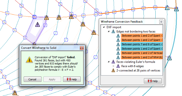
If the wireframe conversion fails, the action pane will display the mismatch in Euler's relation, and the feedback may show issues of three different types in a similar way as the wireframe check. This feedback can be hidden by closing the issue tree view window, and shown by restoring the window from [Objects]→[Wireframe Conversion Feedback].
The issues indicate where the search algorithm got stuck. This need not indicate the exact problem, but often the problem can be found in the neigbourhood.

| Edges not bordering two faces. In a valid boundary representation of a solid, every edge should connect exactly two vertices and border exactly two faces. Issues of this type typically indicate that one of the incident faces to an edge could not be unambiguously identified. The hazard triangles identify the wireframe points that are connected by this edge, and the corresponding curve section is marked with the same color. |

| Faces violating Euler's formula. Euler's relation was discussed in A brief introduction to topology and connectivity of solids, and the indicated faces are where deviation from Euler's relation was detected. As Euler's relation considers the wireframe as a whole, the wireframe deficiencies need not occur at the indicated faces, but often they can be found in their vicinity. |

| 2-connected at vertex pairs indicates the pairs of vertices that make the wireframe 2-connected, meaning that removal of any of these pairs and their incident edges would partition the wireframe into two distinct sets. As indicated in A brief introduction to topology and connectivity of solids, in many cases 2-connected wireframes can be converted successfully regardless, if no other deficiencies are present. If Euler's relation is not complied with, then there are probably other deficiencies that need your attention first. |
It can be a challenge to spot why the wireframe cannot describe a solid unambiguously. These are some of the things that are worth checking against: