|
PIAS Manual
2026
Program for the Integral Approach of Shipdesign
|
|
PIAS Manual
2026
Program for the Integral Approach of Shipdesign
|
For ship and slipway, the following parameters — which are also illustrated in the sketch at the end of this section — must be provided.
This parameter menu has an addition function [PAper size] which can be used to toggle between A3 and A4 paper size for formatting the output.
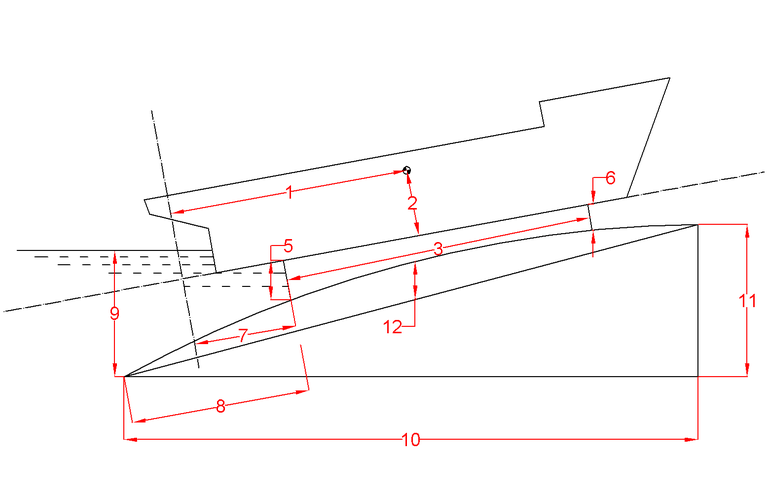
| 1. | Longitudinal center of gravity |
| 2. | Vertical center of gravity |
| 3. | Length of the cradle |
| 5. | Crade height aft |
| 6. | Crade height forward |
| 7. | Distance from aftside of the cradle to APP |
| 8. | Distance from the aftside of the cradle to aftside of the slipway |
| 9. | Waterlevel above the aftside of the slipway |
| 10. | Length of the slipway |
| 11. | Height at the forward side of the slipway |
| 12. | Camber at half length of the slipway |
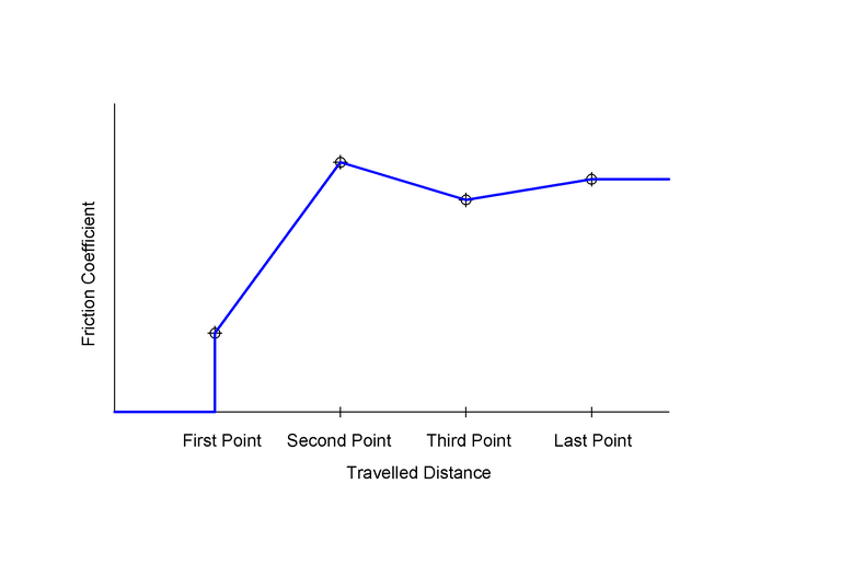
One or more dimensionless friction coefficients as a function of the travelled distance are defined in this input screen, as illustrated in the figure below. The friction coefficient is defined as ship weight / friction force, both in the same dimension. The friction coefficient is assumed to be independant of speed. In this input menu a number (maximum 40) of travelled distance & friction coefficient combinations can be defined. Intermediate coefficients are calculated by linear interpolation, with at the extremities the provisions as illustrated in the figure below:
One or more resistance coefficients of the wetted hull can be defined here as a function of the speed. This coefficient is defined in its simplest form as follows: coefficient = resistance / displacement / speed2 [sec2/m2]. For interpolation of intermediate values the same procedure is adopted as described above.
One or more dragging forces can be defined here as a function of the speed. Intermediate values are calculated as described above.
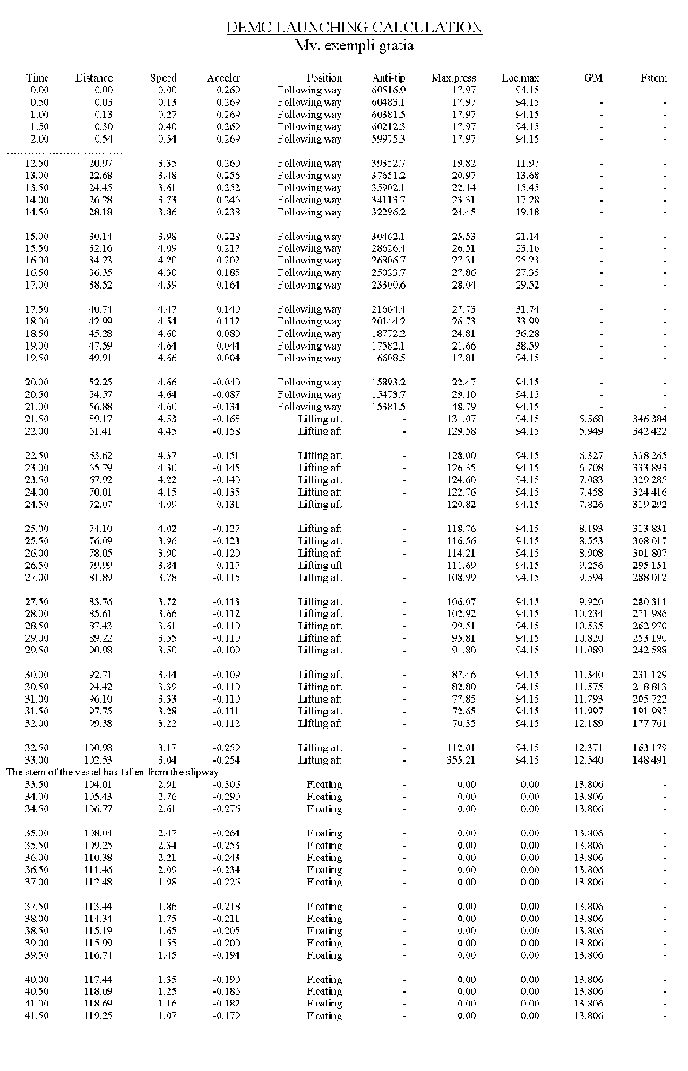
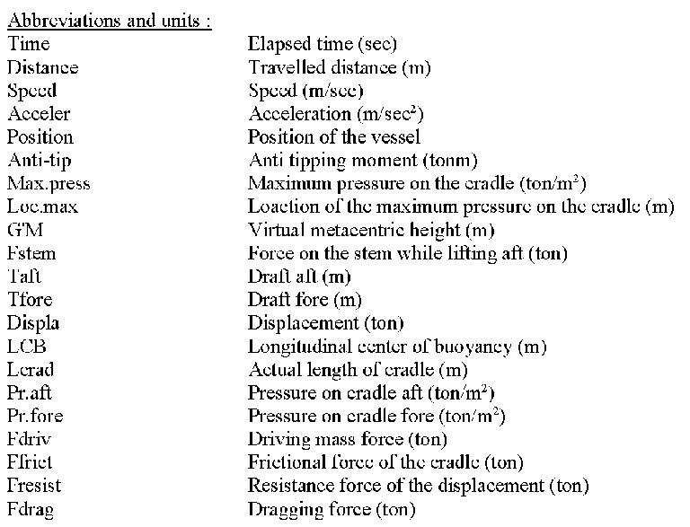
For every step in time the speed, pressure, forces, and travelled distance is printed, as in the example below. By the way, the assumption in the cradle pressure is that it is linearly distributed over the cradle length, and that it is only positive (after all the cradle cannot exert a tension force).
Backups can be made and restored here. Here is also the option ‘Quit module without saving the data’. For details we refer to Data storage and backups.