In the Damage control module, like in the [Damages] module, damage stability calculations can be performed. All mandatory (pre-defined), as well as additional and actual, damage cases can be checked against the relevant damage stability criteria. Furthermore, with the Damage control module countermeasures can be calculated to possibly reduce the negative effects from the damage case on the vessel. Where the damage cases in the [Damages] module only consist out of externally damaged compartments, or more precisely compartments that are flooded from the outside, internal damages can also be defined in the Damage control module.
Layout of the GUI
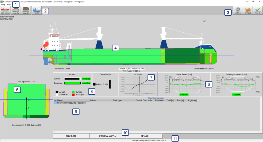
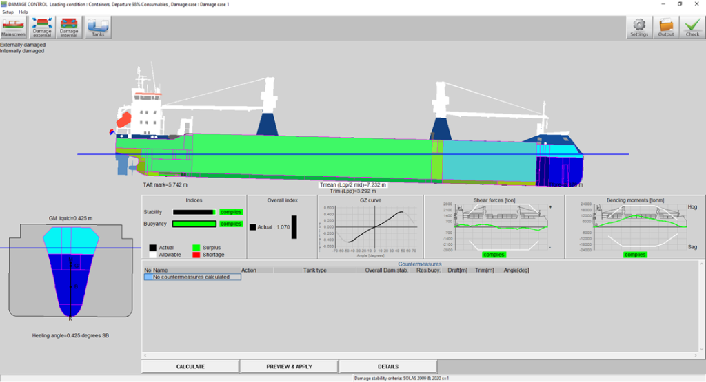
Layout of the Damage control module main screen.
- 1 Menu bar
- Basic functionalities are accessible through the menu bar, see Menu bar.
- 2 Module buttons
- These tool bar buttons provide quick access to the main window and to other parts of the module.
- 3 Function buttons
- These buttons are used to determine and execute the output of the Damage control module.
- 4 Side-view
- Shows the actual wind contour, drafts, actual waterline, line of sight and air draft, all for the selected actual damage case
- 5 Cross section
- Shows heeling angle and initial stability (G'M).
- 6 Compliance windows for longitudinal strength
- These windows indicate compliance with the criteria for the current loading condition. Click on a window for detailed information.
- 7 GZ curve
- Shows the GZ curve of the specific condition.
- 8 Compliance windows damage stability
- These windows indicate compliance with the criteria for the current loading condition and damage case. Click on a window for detailed information.
- 9 List of countremeasures
- A list of countermeasures will be presented here after the calculate option is used.
- 10 Countermeasure buttons
- These buttons are used to calculate the Damage control module.
- 11 Status bar
- Gives the name of the selected damage stability criteria, the calculation status when the countermeasures are being calculated as well as the countermeasure method employed by a countermeasure when one is selected in the list of countermeasures 9
General approach
There are two ways the Damage control module can be used to calculate the damage stability of the vessel. The first is the same as the [Damages] module, listed below:
- Review pre-defined damage cases. The pre-defined damage cases should all comply with the criteria and cannot be edited. They can, however, be viewed and selected for the output.
- Define damage cases. You can create new damage cases by setting compartments to be flooded.
- Select damage cases. To test the loading condition(s) for compliance with the regulations, all pre-defined damage cases should be calculated.
- Print output. Click the [check] button on the [Main Screen] to print damage stability output.
The second way the Damage control module can be used is to calculate the damage stability for an actual, or simulated, damage case and determine the countermeasures that may be deployed to reduce the effect of the damage case.
- Define the actual damage case using the internal and external damage menus via the module buttons 2.
- Calculate the countermeasures via the calculation buttons 10.
- Determine the most suitable countermeasure to be used from the given options in the list of countermeasures 9.
- Preview the selected countermeasure and after accepting it, apply the countermeasure to the loading condition. A new loading condition will be made including the effects of the selected countermeasure after a new name is given to the new loading condition.
- As the result after one countermeasure may not be optimal a second, and later other countermeasures can be applied by repeating steps 2 through 4.
Module buttons
Internal damages
The internal damages window is used to define ‘damages’ in compartments that even in the actual damage case are not connected with the outside water. These damages can occur when for example a pipe bursts or a compartment is (partially) flooded during firefighting operations. All compartments that are not present in the Tank module of [Damage control] are present in the internal damages window. These may include compartments that are also damaged in the external damage module. Compartments that are marked as damaged in the external damage window and which therefore may be already flooded, can be filled in the internal damage window also, just like any other tank.
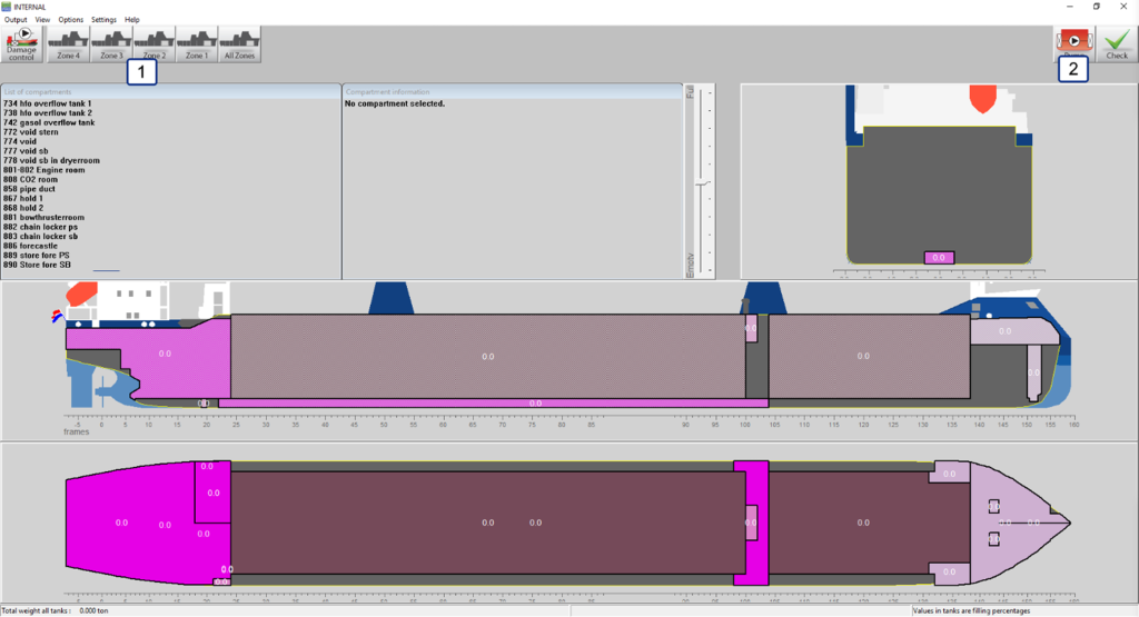
Layout of the internal damages window.
In the internal damage window, the compartments of the vessel may be divided into “zones”, 1, this is done to make it easier to find a specific compartment. The division of these zones is usually related to the watertight subdivision of the vessel. However, the precise division of the compartments of a vessel in ‘zones’ is impossible to predict for the purposes of this manual; therefore, it is recommended that the crew of the vessel is familiar with the divisions used in this module.
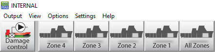
Zone buttons
Two other buttons are present in this window, 2, the “Pump” and the “Check” button. The check button is the same button as the button in the [main screen] and has therefore the same functionality. The pump button is the same as the pump button in the standard Tanks module and has the same functionality.

Pump and Check button.
External damages
The external damages window is functionally the same as the damages window used for the [Damages] module, see The damage definition window for more details. The only difference being that it is not possible to move from this window to the [main screen] of LOCOPIAS or vice versa. This is done to keep the Damage control module somewhat separate from the standard LOCOPIAS modules.
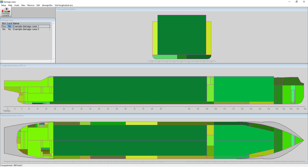
External damages window.
Damages in the main screen
The internal and external damages are presented in the side view and the cross section on the [Damage control] main screen. The externally damaged compartments are shown in a generally darker blue colour than the internally damaged compartments.
Damages in the main window.
Tanks
The [Tanks] button shows all tanks in the same way as the standard Tanks module in LOCOPIAS. However, the calculated draft and trim is determined for the selected damage case. This way, the effect of filling or emptying tanks on the floating position of the vessel in damaged condition can be easily determined. One addition, regarding the standard Tanks module, that may be included in [Damage control] is the cross-flooding function button, 1, which lets the user open or close predefined connections between tanks resulting in changes in FSM and damaged flooding of the tanks. The cross-flooding connection can be opened or closed in the cross-flooding list window, 2, by selecting the desired connection and changing its status.
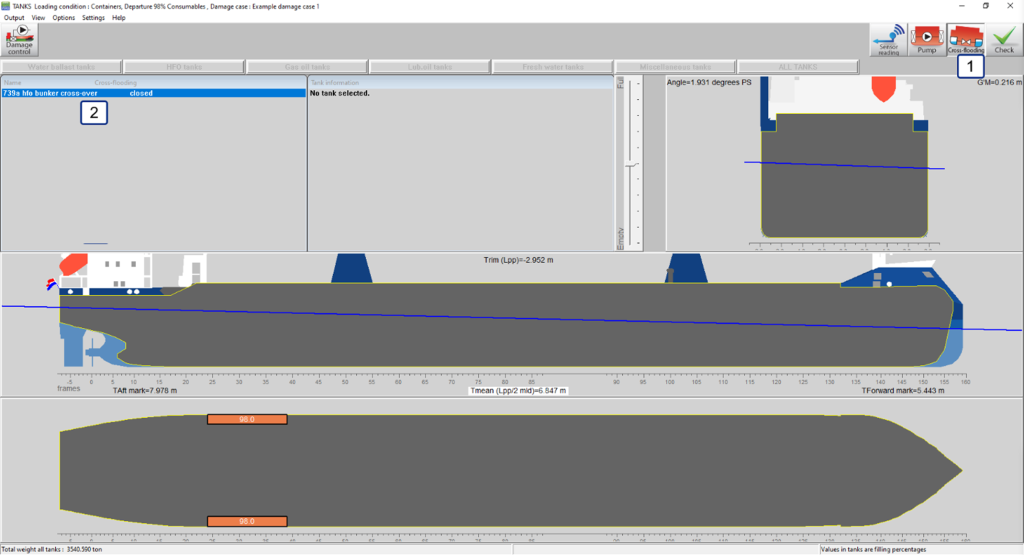
Tanks window.
Countermeasure buttons
Calculate
[Calculate] starts the calculation of the countermeasures that can possibly be deployed to alter the situation of the ‘actual’ damage case. Before the calculations are finished it is impossible to tell whether a specific countermeasure has a positive or a negative effect on the situation. Therefore, both countermeasures that lead to better and countermeasures that lead to worse outcomes are presented, basically every possible countermeasure within programming is presented.
It is important to note that in order to reduce calculation time, only single action countermeasures are calculated. That is to say that only the filling of one tank per countermeasure is altered. This unfortunately, also means that the desired result, e.g., a stable ship, may not be achieved with one countermeasure.
Preview and apply
[Preview and apply] visualizes the application of the countermeasure that is currently selected in the countermeasures window in the Damage control main screen. When this option is selected a pop-up window opens with the question whether or not the user wants to apply the countermeasure and create a new loading condition. When the pop-up is presented and the user has not made a choice yet, the new condition including the actual damage case and the selected countermeasure is visualized. The user can now choose if he wants to apply the countermeasure by selecting ‘yes’ in the pop-up window or if he is not satisfied by the results not applying the countermeasure by selecting ‘no’ in the pop-up window. If the user selects the option ‘no’ the previous condition without the application of the countermeasure is again shown. If the user selects the option ‘yes’ in the popup window, then a new loading condition is made where the countermeasure is applied to the previous condition. The module will automatically select this new condition so the user can calculate the next countermeasure if necessary. Every time a countermeasure is applied, a new loading condition is made in the manner described above, this is done so the user can easily revert back to the condition before a countermeasure was applied. This also allows for the user to quickly recap all countermeasures that will have to be undertaken without the need to write anything down.
Details
[Details] shows the details of the selected countermeasure, a summary of the condition of the vessel before the countermeasure is applied and a summary of the condition of the vessel after the countermeasure is applied. The details of the selected countermeasure include the action undertaken and the particulars of the tank that the action is applied to, i.e., the filling, weight, volume, etc.
Compliance windows
Apart from the buttons there are a number of windows, 6 7 8, that can be seen in the main screen of the Damage control module. The windows that may be present on the main screen are;
- The damage stability index window, where the actual damage stability index is shown as well as the maximum. The damage stability index describes the difference between the actual VCG’ for the actual damaged condition and the maximum VCG’ where the damage stability criteria are met.
- The reserve buoyancy index window, where the reserve buoyancy is presented. The reserve buoyancy index describes the distance between the water and the margin line or open openings.
- The overall index window, where the overall index is presented. This index is calculated using the following formula and boundary conditions;
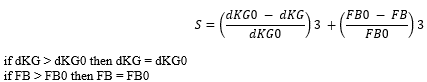
Overall index formula.
- The GZ curve window, where the GZ curve of the damaged vessel is presented.
- The Shear forces window, where shear forces are visualized together with the shear force limits of the vessel.
- The Bending moments window, where the bending moments are visualized together with the bending moment limits of the vessel.
Function buttons
Settings
[Settings] in
[Damage control] only lets you change whether or not you want to include intermediate stages in the damage stability calculations made using the Damage control module.
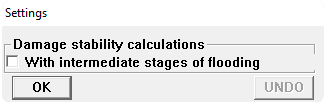
Damage control output settings.
Output
[Output] gives the user a number of options. First of all, the choice whether the user wants the output of all selected damage cases, (selected in external damages), or the output from the actual damage case, (the one visible in the
Main window layout).
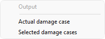
Damage control output option.
When the user has selected the output for the actual damage case, four options become available. The user can select one of these four output options;
- Damage control report, which prints a comprehensive output of the damage stability results and the longitudinal strength in damaged condition.
- Damage stability, which prints the results of the damage stability calculation for the actual damage case.
- Damage stability summary, which prints a summarized version of the above-mentioned calculation. The summary only includes the final results of the calculation.
- Longitudinal strength, which prints the longitudinal strength output in the same way as the intact longitudinal strength output, only this output includes the influence of the damaged or otherwise flooded or emptied compartments.
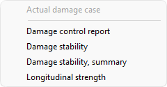
Damage control output for the actual damage case.
When the user selects the output for all selected damage cases two options become available. The user, again, can chose one of these options;
- Damage stability, which prints a complete output of the results of the damage stability calculations for all selected damage cases.
- Damage stability summary, which prints a summary of the above-mentioned calculations. The summary only includes the final results of the damage stability calculations.
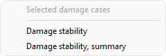
Damage control output for the selected damage cases.
Check
[Check] in
[Damage control] has largely the same function as it does in the
[Main screen] of
LOCOPIAS, it gives a quick overview of the condition of the vessel in damaged condition. It does this only for the actual condition that is presented visually in the Damage control main screen.