|
LOCOPIAS Manual Seagoing Vessels
2026
Loading Computer Software
|
|
LOCOPIAS Manual Seagoing Vessels
2026
Loading Computer Software
|
Show and manipulate defined cranes and, if applicable, ballast tanks in a Graphical User Interface, an example of which is depicted below. A description of the labeled elements follows.
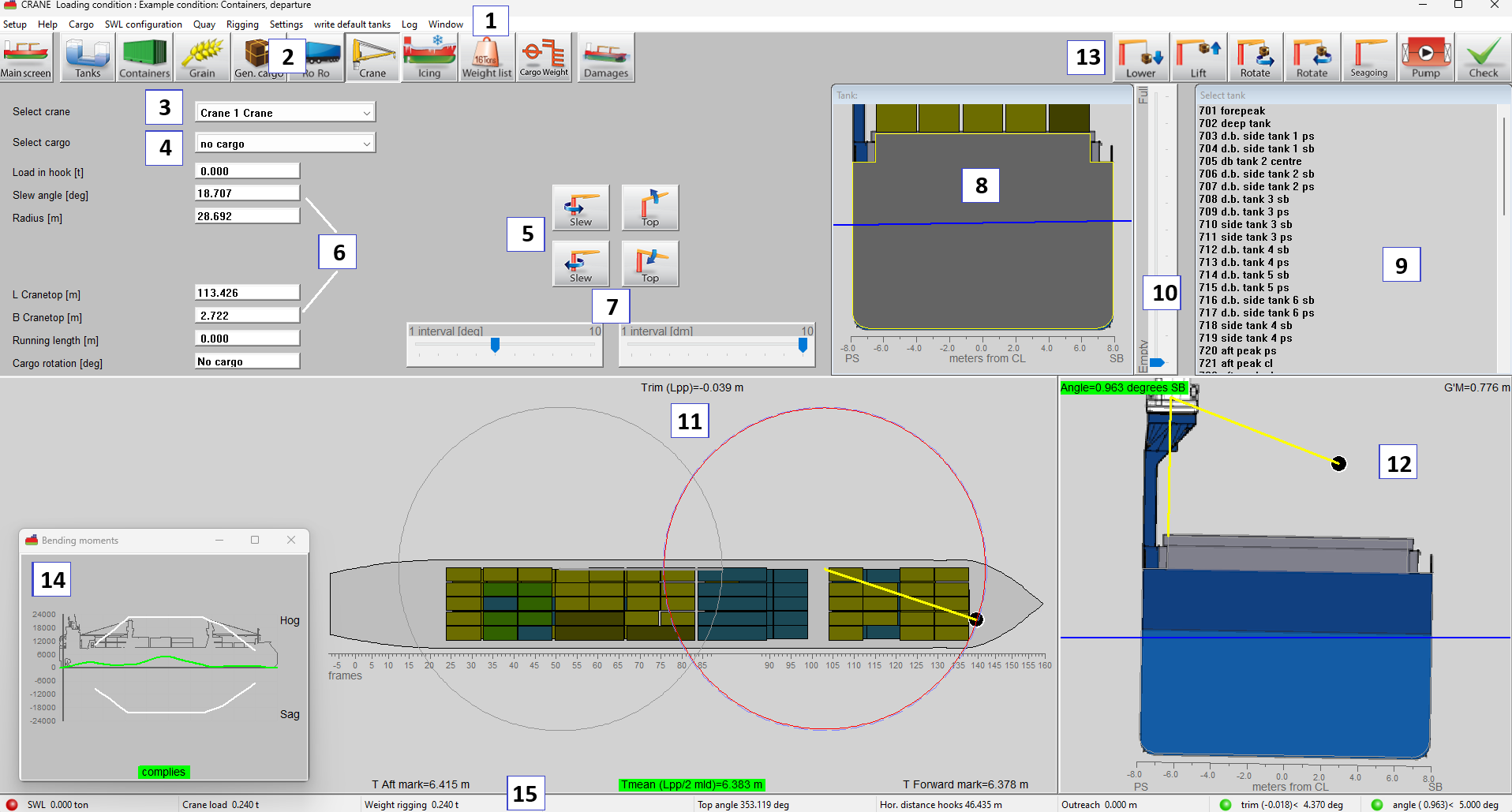
Basic functions are accessible via the menu bar. In addition to these, the menu bar also provides access to the following advanced functions:
Cargo: Opens the cargo menu window, where each line represents a cargo entry. User is able to define and modify the cargo entries via this menu. Add a new cargo entry with the New option.
SWL Configuration: Safe Working Load. By selecting this option a popup window will open in the main screen. Via this window, the user can select the safe working load table for each crane.
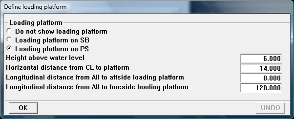
Quay: Define a quay to simulate discharging or loading operations. Its position and dimensions can be visualized in the top and cross view windows via the Quay menu option.
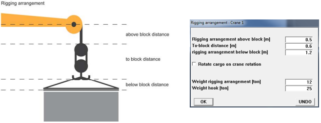
Rigging: Use this menu to set the minimum vertical clearance between the crane tip and the hoisting point, as determined by the rigging configuration.
(Activity) Log: Opens a window on top, in which all crane and ballast operations are listed. This log can be printed. Reset empties the log.
These buttons navigate to another module, or back to the main screen.
Choose the crane you want to manipulate.
From the drop-down box choose the cargo you want to load.
Use the buttons to steer the crane or manipulate cargo parameters.
Enter values directly here.
Set interval step for meters and degrees.
View on the (first) selected tank in a cross section.
Select a tank for ballasting. For transfer of tank contents between tanks change to the [Tanks] module 2.
The track bar can change the filling of the selected tank.
The circles in the top view indicate the maximum and current radius of the crane for the upright vessel.
In the cross section view the heeling angle and position of the crane can be seen.
Specific functions to operate the crane, manipulate cargo, pump tank contents and verification of the current loading condition.
Direct verification of stability or strength. This dynamic repositionable window can be activated by the menu bar function [Window]→[Result windows].
There are two ways to define cargo:
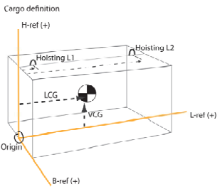
Choose the crane you want to operate 3 and either enter a weight 6 or select a defined cargo item 4. If defined cargo is selected, firstly hoisting point 1 is used. The minimal vertical distance from the crane top to the hoisting point due to rigging arrangement can be defined under [Rigging] in the menu bar. Also weight of rigging arrangement and hook can be defined here. The weights entered here will be added to the load in the hook automatically.
Use the buttons on the dashboard 5 to operate the crane or cargo suspended from the crane. It is also possible to type a specified value in the edit boxes 6 showing the actual values. For simulation of discharging or loading, it can be useful to define the quay. The position and dimensions of the quay can be made visible in the top and cross view windows by selecting [Quay] in the menu bar.
If the vessel is equipped with two or more cranes a dual crane operation can be performed. This requires a dimensioned cargo item. To start a dual crane operation:
During a crane operation, ballasting may be required. Select a ballast tank 9 to perform a ballast operation with. Now use the track bar to change the volume of the selected tank. If the [Pump]-button is selected, the fluid is pumped between two selected tanks in 9. Under the menu [Settings]→[View tanks] you can choose to view all tanks available for ballast operations in the top view or only the selected tank.
If Safe Working Load tables, and/or allowable heeling and trim angles are preprogrammed, these are also checked for compliance. The cranes working radius circle will turn red in the top view 11 when the Safe Work Load is exceeded.
In Check more information can be found about verification of the loading condition.
All crane operations can be stored in a [Log]. The log can be printed by clicking the [Print] button in the log window.