|
PIAS Manual
2019
Program for the Integral Approach of Shipdesign
|
|
PIAS Manual
2019
Program for the Integral Approach of Shipdesign
|
The calculation is based on the methode of M. Oosterveld & P. van Oossanen, NSP 1974, and is valid for pitch/diameter ratios between 0.6 and 1.4. The applicable blade numbers and blade area ratios are listed in the table below:
| Number of blades | 2 | 3 | 4 | 5 | 6 | 7 |
| Expanded area ratio | 0.3 | 0.35-0.8 | 0.4-1.0 | 0.45-1.05 | 0.5-0.8 | 0.55-0.85 |
The calculation is based on the method of M. Oosterveld, ‘Ducted propeller characteristics’, RINA 1973, and is valid for pitch/diameter ratios between 0.5 and 1.6, and for the following propeller/nozzle combinations:
| Propeller | Nozzel | Number of blades | Blade area ratio |
| Ka 3-65 | 19A | 3 | 0.65 |
| Ka 4-55 | 19A | 4 | 0.65 |
| Ka 4-70 | 19A | 4 | 0.70 |
| Ka 4-70 | 22 | 4 | 0.70 |
| Ka 4-70 | 24 | 4 | 0.70 |
| Ka 4-70 | 37 | 4 | 0.70 |
| Ka 5-75 | 19A | 5 | 0.75 |
| Ka 5-100 | 33 | 5 | 1.00 |
The different nozzles have the following particulars, where L is the length of the nozzle and D the propeller diameter.
Nozzle 22 and 24 are similar to 19A, except for the L/D ratio which is higher, which is favourable for tugs. Nozzle 37 has a thick trailing edge which results in better performance with power astern. Nozzle 33 has a higher cavitation limit which is favourable to decrease the level of vibrations and noise.
The calculation is based on the method of R. Gawn, ‘Effect of pitch and blade width on propeller performance’, RINA 1952, and has the following application area:
The calculation is based on the method of A. Yazaki, ‘Design diagrams of modern four, five, six and seven-bladed propellers developed in Japan’, 4th Naval Hydronamics Symposium, National Academy of Sciences, Washington, 1962. The parameters should be within the following limits per propeller:
| Propeller name | N-AU 3-35 | N-AU 3-50 | AU 4-55 | AU 4-70 | AUw 6-55 | AUw 6-70 | AUw 6-85 |
| Number of blades | 3 | 3 | 4 | 4 | 6 | 6 | 6 |
| Expanded area ratio | 0.35 | 0.5 | 0.55 | 0.7 | 0.55 | 0.7 | 0.85 |
| Pitch/diameter ratio | 0.4-1.2 | 0.4-1.2 | 1.0-1.6 | 1.0-1.6 | 0.9-1.5 | 0.9-1.5 | 0.9-1.5 |
Here an input window with ship hull parameter appears. Excepts for the drafts, they will only be utilized for the estimation of wake and thrust deduction coefficients (by Holtrop & Mennens method), not for the propeller calculations as such. If the resistance values have been transferred from Resist to Prop, those parameters are already filled in, because they have already been defined in Resist and have been cotransferred. So, for their description reference is made to Input data resistance prediction.
In this input screen you can enter up to twenty speeds with the resistance. Enter the speed in knots and resistance in KN.
This option is for calculating a propeller at a given speed and resistance when the number of revolutions and the pitch of the propeller is unknown. The determined propeller has a maximum possible open water efficiency.
This option calculates a propeller at a given speed, resistance and (range of) number of revolutions. The pitch is determined so that the delivered shaft horse power equals the required shaft horse power. The previous calculation option (maximum efficiency) calculates all combinations of speed and diameter. The present revolutions variation does, however, its calculations only for the very first diameter.
This option is to determine the resistance at the trial trip. All propeller characteristics have to be defined by the user. Using the defined propeller dimensions the resistance is calculated.
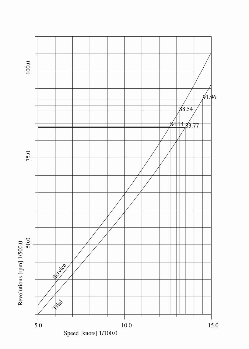
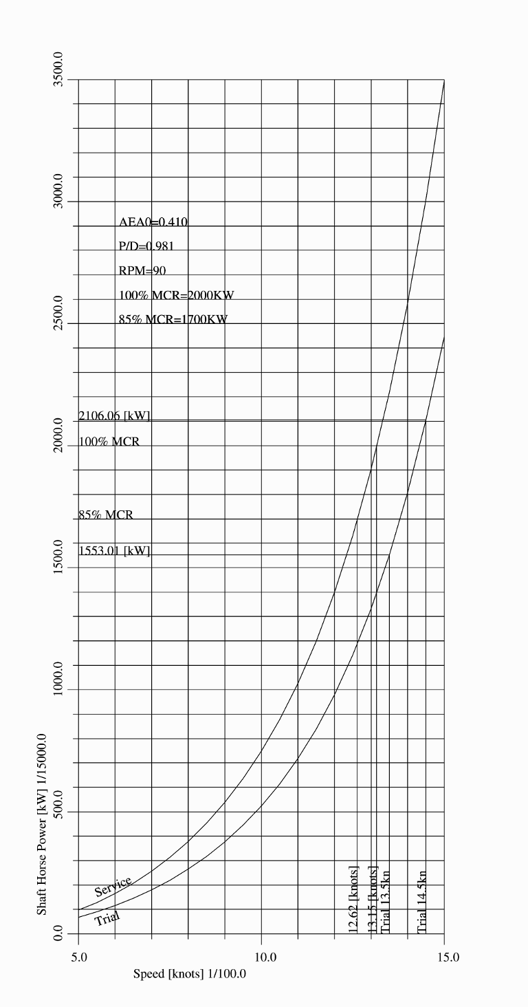
The following menu will be displayed on the screen, where with the first two options the speed-power curve is actually computed and plotted. The first option is for a fixed pitch propeller (and consequently varying revolutions), and the second for a controlable pitch propeller, with fixed revolutions. The other options can be used to configure the nature and content of the graph.
For a propeller with fixed dimensions a graph can be plotted, which gives the relationship between the speed and the required shaft horse power. With the standard version the calculation can be performed for a fixed pitch propeller. The graphical extensions also allow calculations with a controllable pitch propeller. If there are any losses due to pitch variation, these can be defined by an allowance on the required power. The graph shows the shaft power at the speeds you specify. It is therefore important to specify sufficient speeds, with a small interval to obtain a smooth graph. Below you will find an example of such a graph.
With this option the thrust force can be calculated for a range of speeds, by varying the revolutions. The available shaft power (in KW) is defined at option 3, by entering the power instead of resistance. If the speed is zero, the wake factor and the thrust deduction fraction are default set to 0.05. This value can be changed by entering the wake and thrust factors by hand. The thrust force at speed zero is the bollard pull. The calculated thrust force reduced with the resistance, at speeds larger than zero, results in the available thrust force, for example for towing fishing gear.
With this option the thrust force can be calculated for a range of speeds, by varying the pitch-diameter ratio, for a fixed number of revolutions (for which the first revolutions value is taken from the range as given in option 2 ( Input of propeller data. Also for this option the shaft power should be given at option 3, by entering it (in KW) in the ‘Resistance’ column. For wake and thrust deduction factors, as well as bollard pull — the same remarks as from the previous option apply.
This option pops up a window with a power curve, as discussed in Calculate speed-power curve with fixed propeller dimensions. However, here, in cloud context, this diagram is dynamic, which means it is recomputed and redrawn every time when data in the cloud which affects the power results changes. For more information on the cloud reference is made to Local cloud: simultaneous multi-module operation on the same project.
With this option design version can be managed, with a mechanism as described in Data storage and backups.