PIAS Manual  2024
Program for the Integral Approach of Shipdesign
Graphical User Interface of planes and compartments

GUI components

layout_GUIoverview640.png
GUI.

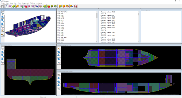
An example of the GUI (Graphical User Interface) is shown above. The GUI may contain nine sub windows (from which some can be switched on or of with functions as discussed in View):

  • Three orthogonal cross sections, namely a transverse, longitudinal and horizontal.
  • A 3D (rendered) view.
  • A tree view window with a tree of compartments and subcompartments.
  • A tree view window with physical planes.
  • A tree view window with reference planes.
  • A text windowlet showing the total volume of the selected (or, the pointed) compartment.
  • A constraint management window in which design objectives are shown, as well as the discrepancy between objective and reality. For the time being, this constraint management facility — from which purpose and operation is discussed here — remains undiscussed in this manual.
Attention
The two orthogonal longitudinal sections here in the GUI are in the end derived from the ship hull shape, which as a rule will be a frame model representation (please refer to Hull form representations for an overview of the different ship hull models applied by PIAS). Other sections can theoretically not be created with guaranteed correctness, on basis of such a frame model, actually a curved surface model is required for this task. In order to create these kind of sketches, PIAS contains extensive algorithms which anticipates on quite some special situations. The result is that only by rare exceptions the longitudinal sections are not properly drawn. In such an occasion there is no reason for suspicion, for it is only a visual affair, the computation results are not affected.

Right at the bottom of the GUI window a status line is displayed, subdivided in five boxes:

  • The first box contains a short explanation of the function of the menu bar, when the mouse pointer stands on it.
  • The second box displays the selection mode (see Left mouse button and modus).
  • The third box dynamically displays the coordinate (L, B and H) of the pointer position in the orthogonal views.
  • The fourth box dynamically displays the name of the physical or reference plane that is closest to the mouse pointer.
  • The fifth box dynamically displays the name of the compartment and/or subcompartment where the mouse pointer stands above.

Furthermore, in the upper bar the GUI has a number of functions that have been subdivided in subfunctions. Those functions can either be carried out directly, or can be ‘hanged’ to the mouse button, which mechanism is discussed in How long stays a function assigned to a mouse button?. The function bars under [Compart], [Refplane] en [Plane] are subdivided by a horizontal dividing line. The functions above that line are only related to the tree view window in question, the functions under the line are generally applicable.

General operations and modus

Mouse buttons

The mouse buttons are used as follows:

  • The left button can be used for two things, namely a) the selection of compartments, physical planes and reference planes, or b) performing functions with it.
  • Pressing the right button and subsequently moving the mouse is for display. In the three orthogonal views that is choosing the intersection locations (unless one has opted for pan at the tool bar at the left side of that window). And in the 3D view that is default rotation (unless one has opted for another display function at the tool bar at the left side of that window, for example, pan or clip).
  • Shortly clicking the right button in the 3D view brings up a specific menu with which colors, translucency and lighting can be set, or a screen print or 3D model (in VRML-format) can be stored in a file, see Operation in the 3D subwindows for a more detailed explanation of the possibilities in the 3D view.
  • Keep on pressing the middle button and then moving the mouse is panning.
  • The mouse wheel is zooming, as well in the 3D view as in the orthogonal views.

Furthermore, one can carry out the (for MS Windows) usual actions in the tree view windows such as dragging of compartments, subcompartments, physical planes and reference planes. With function button <F2> one can change a name into such a tree view window.

Left mouse button and modus

The left mouse button is meant default for indicating or selecting of ship's items — compartments, physical planes and reference planes — but it is also possible to assign a function to it, which is carried out later when such ship's item has been indicated. When such a function (for example function [Plane], subfunction [Edit], with which data of physical planes can be modified) has been activated, it is shown in the second block of the bottom status row. When the box displays ‘Select’, this means that the left mouse button is in the default position: select. What is exactly selected depends on the selection modus, which can have four positions:

Auto
This is the most extensive position; herewith the nearest item is selected, which may be a compartment, physical plane or reference plane. At a physical plane, the <Alt> key can be used, see the discussion at ‘planes’ below.
Compartments
With which only compartments are selected (see note below).
Planes
With ‘Planes’ only physical planes are selected. It may happen that physical planes are very close to each other and visually indistinguishable, in which case the left mouse button in combination with <Alt> can be used. Then a box will pop up with the (maximally four) nearest planes, from which one can be chosen.
Reference planes
Only reference planes are selected herewith.
Piping
In which the selection is restricted to piping systems. If subsequently a pipe line is double-clicked, that pipe is opened in the piping definition GUI, which is discussed in Pipe lines and piping systems. The piping is deliberately not included in the ‘Auto’ setting (from a few lines above); because the pipes cross everything else, they should be explicitly selected.
Attention
Instead of selecting a compartment, it could occasionally be desirable to select a subcompartment. However, in general that would be somewhat difficult, because in the 2D views compartments are shown instead of subcompartments. For this reason, in due time, the [view] option (see View) will be extended with the ‘subcompartment’ setting as an alternative to the current ‘compartment’ setting. The two will be mutually exclusive, so either the compartments are shown, or the subcompartments. And the object of selection at this point in the manual follows this view- setting. This mechanism may, however, induce a side effect: a single specific action will imply more or less a certain selection, for example if in the compartment tree a compartment is selected, then it might be obvious to select a compartment as well in the 2D views, mutatis mutandis for a subcompartment. However, such ‘logic’ might be in conflict with the present view compartment/subcompartment setting, and for that reason in such a case the program will switch automatically to the view setting which matches this action ‘logically’.

How long stays a function assigned to a mouse button?

This is no principal matter, it is a choice, Layout can be made thus that it is assigned once, or permanently, or otherwise, in principle this does not matter. But users may have different wishes, and that's why that can be set, in Layout project settings and function colors is explained how this works. There are three options:

Never
Then the mouse function always remains attached to the left button (until one chooses another).
Cancel structural commands after use
With this setting, commands that cause an important modification in the arrangement structure (such as adding and removing of planes) are removed as mouse function after single use. This prevents that planes or compartments are unwantedly added or removed in the event of fast clicking.
Cancel all commands after use.
Herewith any function is removed as mouse function after single use, and therefore one has to assign any command to the mouse button repeatedly. Apart from that, at all times the user can detach the function from the mouse button with the key <F12>

Operation in the 3D subwindows

layout_drieDaanzicht640.png
Three-dimensional sub window.

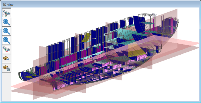
At the left side in each three-dimensional subwindow is a number of buttons that are specifically related to that subwindow. When the right mouse button is pressed permanently, the [rotate] or [pan] function is carried out, depending on what has been set. By pressing the right mouse button shortly, a popup menu appears with which one can carry out non-modelling operations witih the ship subdivision model. These are available in four groups, are being discussed in much more extent in Rendered views, but summarized their functions are:

  • [View]: herewith one can carry out the same operations as with the buttons at the left side, which have been discussed above. Besides, there is still the function [(in)visible], with which one can set which individual parts of a ship are (in)visible.
  • [Edit]: with this function the position and intensity of external light sources can be set. One can also change the colors, reflection characteristics and transparency of objects or background
  • [File]: with this function one can save the present picture to file (in VRML or BMP format), print with the printer or copy to clipboard. This function only regards the picture, it has nothing to do with the file saving of Layout.
  • [Setup] contains two obsolete configuration options.
Attention
With emphasis a tools is recomended which can assist to determine from which side an object is viewed. This is the orientation box, from which purpose and operation is discussed in View.

Shortcut keys

In order to speed up work it can be practical to use shortcut keys. The following are available for this:

  • In the tree view windows the <Insert> and <Delete> keys for resp. adding or removing of a (sub)compartment, reference plane or physical plane. After <Delete> at (sub)compartment, the (sub)compartment can be sticked in again (possibly at another position), so this button rather has the meaning of ‘cutting’ than of ‘removing’.
  • In the tree view windows the <Home>, <End>, <Page Up> and <Page Down> keys in order to jump resp. to the top of the list, to its bottom, to the upper line of the window and to the lower line.
  • In the tree view windows the <F2> to alter the name.
  • <F12> to detach a function from left mouse button (see How long stays a function assigned to a mouse button?).
  • As side-effect of Windows, any function in the upper bar can be called with the key combination <Alt><function letter>.
  • In due course, other <F> function keys will be assigned to the functions that are mostly used.

The shape of a plane (the green dots)

layout_yellowdots800.png
Defining the shape of a physical plane with the green dots.

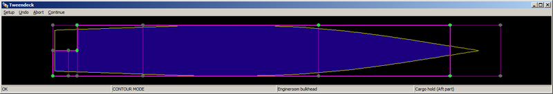
An important function of Layout is the addition of planes. These not necessarily need to extend over the entire ship, but can also be in a part of it. This shape is entered by means of the plane contour, which is controlled by the ‘green dots’, as they are called in the manual. Its background is discussed here in more detail. This all takes place in a popup window as displayed in the above figure, where you can see that the shape of the plane has been recorded with only three green dots.

What is shown there is the cross-section of the plane, with the chosen contour indicated in purple (at least, that is the default color, the user himself can choose another color at the Setup menu, see also Layout project settings and function colors). The contour can stop at the intersection with other planes, so one does not enter coordinates here, one chooses to which other, already present, planes the contour extends. A topological definition has been obtained in that manner, from which results, for example, that when the position of another plane changes, this contour also changes. The main idea here is that a user can enter the desired contour by indicating points of these other planes, through which that contour has to go. By the way, one need not indicate all points, also in the event of only a few points the program itself chooses the most evident contour, see the example from the figure where the contour has been recorded with only four indicated points (the green dots). More precisely, indicating occurs as follows:

  • When one stands with the mouse pointer on or near a point, then the dot can be switched on or off with the left mouse button as ‘wanted’ (green).
  • When one stands with the mouse pointer near a connecting line between two points, then that piece of line can be switched on or off with the left mouse button as ‘wanted’ (green).
  • When one stands with the mouse pointer on or near a point, then the dot can be switched on or off with the right mouse button as ‘unwanted’ (red).
  • Idem for unwanted connecting lines (red).

In the event of a new plane, one can directly start to switch on/off. In the event of an already existing plane, there is protection against accidental modification, which is called the ‘contour modus’. That contour modus is initially ‘off’ (that is also reported in the status line at the bottom of the window) so nothing can be changed. With menu option [Setup], suboptie [Contourmodus] one can switch this on. Further options from the upper bar menu are:

  • Undo, undo the changes, and put the original contour back.
  • Abort, abort this action and stop with this contour changing window.
  • Continue, stop with this contour changing window and process the change in the ship's model. When one presses on the right upper cross of the window then it is clear that the user wants to stop with this window, but it is not clear whether the changes have to be included in the ship's model. When there actually are changes, that question is asked again.

GUI functions

The purpose and the operation of various functions to be chosen from the upper bar are discussed below. There are two types of functions, namely those with a direct effect (since nothing else has to be indicated) and those that are assigned to the left mouse button, because something has to be indicated later on to which this function is applied. At any function below is mentioned which type it is.

Setup

Clear action

The action that is attached to the left mouse button at that moment is removed from it with this. Type of function: direct.

Selection mode

Herewith one can choose one of the four selection modi, as explained in Left mouse button and modus.

Setup

Herewith one calls up the menu with program settings, which is discussed in more detail in Layout project settings and function colors.

Colors

Herewith one calls up the menu with which the colors of the various ship's components can be set. This is a limited version of a more general menu for setting ship's components, which is discussed in more detail in Names and color per part category.

View

First of all, one can indicate here which things you would like to be presented in the GUI. You may select from:

  • Planes, these are the physical planes and. When these have been made invisible, then the physical planes tree view window also disappears, because this has become useless. Likewise, functions related to physical planes cannot be activated then. Also a third choice exists, between on and off, which is separating planes on. With this choice only those parts of the physical planes will be drawn which constitute real separations between compartments (or, to be more precise, between subcompartments of type ‘space generated between planes’). This gives a more realistic picture, however, please bear in mind that this is a drawing switch only; in the underlying model the physical planes still extend, also if the separate parts of the same compartment. In ‘outside’ output, such as to the subdivision plan, always the separating planes on method is used — regardless the switch setting here in the GUI — because this is most genuine.
  • Reference planes, the reference planes. When these have been made invisible, then the reference planes tree view window also disappears, and functions related to reference planes cannot be activated.
  • Hull, the hull lines (or planes), only applies to the 3D window.
  • Compartments, applies to the 2D windows as well as the 3D window.
  • Piping, all pipe lines, from which the definition method is discussed in Pipe lines and piping systems, applies to the 2D as well as the 3D windows.
  • Compartment Colors, where the system of compartment coloring can be chosen; the options are:
    • Uniform, where all compartments get the same color. There may be a difference in color after specific program actions, such as in the event of a just cut or generated compartment (these colors can be set at Layout project settings and function colors).
    • Individual, where any compartment gets its own coulor (automatically determined by the program).
    • Per weight group, where a compartment is colored in conformity with the color that applies for the weight group assigned to the compartment. These colors can be set as discussed in Define weight groups.
    • Compartment Overlap, here the program conducts an overlap test between compartments, where one can deduce from the color whether the compartments have been defined uniquely and non-overlapping, as it should be:
      • Green: good.
      • Background color: this piece of a ship is not covered by a compartment, the compartment definition is therefore not complete.
      • Red: two or more compartments overlap here.
  • Compartment Volume, which makes the volume of the selected (or, alternatively, pointed) compartment to be shown in a text windowlet.

Plane

Here the menu options above the horizontal dividing line also apply to the tree view, and those under the line to the graphical windows. For the time being, the first group consists of only one function:

Sort

With this command the compartments in the tree view are sorted. This can be done on four criteria, namely on name, position, type and abbreviation. The sorting can be undone again with Undo. Type of function: direct.

Draw

With this function one draws a plane interactively. The operation is as follows:

  • Choose this function.
  • Go to the orthogonal view where the plane must be perpendicular to.
  • Go to an endpoint of the plane and press the left mouse button. There will appear a cross-hair.
  • Go to the other endpoint, and press the left mouse button again. There will appear a second cross-hair, with a connecting line.
  • The bulkhead will be generated perpendicular to the view, through that line.
  • In general, the line will not fall in an orthogonal plane accurately, whereas that was perhaps intended. That's why the program offers the opportunity of fine-tuning. There one can choose from: - Consider the bulkhead to be orthogonal (through the mean location of the line)
    • Idem, but with the possibility to adjust the location exactly, by typing a size.
    • As drawn (possibly angled).
  • Afterwards appears a pop-up window with the ‘green dots’ (see The shape of a plane (the green dots)) so positioned that an as reasonable as possible part of the line is covered by the bulkhead. Is this not satisfactory, then one can still adjust the level of extension of the bulkhead by means of the yellow dots. Type of function: left mouse button, because the location and direction of the plane have to be entered later on by means of drawing.

New

With this function the popupbox from Popup menu for geometry of points or planes comes up, which is used to add a plane that extends over the entire ship (from stern to bow, or from bottom to top) at the beginning. Afterwards can be indicated through the ‘green dots’ (see The shape of a plane (the green dots)) that the plane extends over a more limited part. Type of function: direct.

Insert

With this function one adds a plane in one indicated compartment. Afterwards, one can still indicate through the ‘green dots’ that the plane extends over a larger part. Type of function: left mouse button, because the compartment where the plane will appear has to be indicated later on.

Remove

A plane is removed with this function. After the removal of the plane, excess subcompartments may remain. These are removed according to the order of the (sub)compartment list, i.e. when several subcompartments of the type ‘space generated between planes’ refer to the same space, then the first ones are removed and the last of all remains. Type of function: left mouse button, because the plane to be removed has to be indicated later on.

Attention
Plane A can be a boundary in another plane, plane B. If plane A is removed then B will become larger as a result, because it will lose its boundary. This change in B may in turn introduce other changes in other planes, for which B was the boundary. Etc. etc., that can result in a chain reaction of changes. It may be that the result of changes is unexpected, or even undesired. In that case one should manually adapt the changed layout to the human insights.

Edit

The features of a physical plane can be changed with this function, see Menu with properties of planes for details. Type of function: left mouse button, because the plane to be changed still has to be indicated.

Geometry

With this function the contour (and therefore the shape) of a plane is changed. Type of function: left mouse button, because the plane to be change still has to be indicated. After having indicated the plane, a window pops up with the shape of the plane, where one can change the contour by means of the ‘green dots’ (see The shape of a plane (the green dots)).

Attention
If a planeis modified in such a way that parts are discarded, then the remark given just above at ‘Remove’ is also applicable here.

Copy

Herewith one can copy a plane. Type of function: left mouse button, because the plane to be copied still has to be indicated. The operation is:

  • Choose this function.
  • Point at the plane to be copied.
  • A pop-up window of the copied plane appears, already filled with the copied parameters. Change the name and position in that window (NB the orientation (position of the plane) cannot be changed, so one is not able to copy a transverse bulkhead to a deck).
  • Press the OK button, and the copied plane is added to the model.

Compartment

These menu options have been subdivided in two groups, those above the horizontal dividing line regard the compartments tree view, those under the line are applicable in the graphical windows. We start with the first group:

Compartments Tree view

The compartment tree contains the compartments in the main branches, and under each compartment the subcompartments. With this command one can collapse and expand all branches at once. Apart from that, one can of course also collapse or expand an individual branch with the + for each compartment. Type of function: direct.

Sort

With this command the compartments are sorted in the tree view. This is possible on two criteria, namely on compartment name, and on location (where the compartments are sorted in length, breadth and height direction). The sorting can be undone with Undo. Type of function: direct.

Newcompart

Herewith a new, and empty, compartment is added in the tree, just below the compartment that was selected at that moment. In order to control at which location in the tree the compartment is exectly added, this command can only be given from the compartment tree window. Type of function: direct.

NewSubcompart

Herewith a new subcompartment is added under the compartment that was selected at that moment. The subcompartment only has a default shape and type, which has no meaning, nor any connection with something else. Type of function: direct.

Cut

Cut a compartment or subcompartment. The type of function depends on the sub window from where the function was activated; in a compartment treeview the function has direct working, from a 2D window the function is assigned to the mouse button. By the way, the <Delete> key does exactly the same.

Paste

Paste a compartment or subcompartment. That object is then placed after the then selected compartment or subcompartment. Type of function: direct.

Undocut

Undoes the cutting of a (sub)compartment. Type of function: direct.

Remove eMpty

Removes all empty compartments (those compartments that have no subcompartments). This function can be practically used after a number of compartments no longer has subcompartments after dragging (graphically, or in the compartment tree). Those can easily be removed in this manner. Type of function: direct.

Edit

This is the first function of the list that is applicable in the graphical windows, and therefore not in the tree view. With this function one enters the detail window of a compartment, which is discussed in more detail in Compartment definition window. Type of function: assign to left mouse button.

Assign

Compartments and spaces as they are generated between planes have been linked. This link is as much as possible maintained, so when, for example, a new plane is added then additional compartments will be generated for that, the name and other features of which can be adjusted later on by the user. But if one has removed a compartment with, for example, [Cut] or the <Delete> key the space in question still exists, but it is no longer linked to a compartment. With this function, [Assign], a new compartment is added that is linked to the space. That new compartment still has default parameters, such as name and specific gravity, but these can simply be changed later on. Type of function: assign to left mouse button, because the space to which a new compartment must be assigned has to be indicated afterwards in one of the orthogonal cross-sections.

Swap

When a plane is added that runs through a subcompartment, that subcompartment is divided in two parts, while the features of the original subcompartment are assigned to one space, and a new subcompartment is made for the second space, the features of which have to be filled in in more detail (except for its shape, of course). This choice is arbitrary, and it might very well be the intention of the designer that the original subcompartment is assigned to that second space. When this is the case, one can turn this assignment with this function, [Swap], again (and also turn it back again when one is mistaken). Type of function: left mouse button, since the space to be swapped still has to be indicated.

Recombine

Subcompartments are hanging under compartments, and its organisation is completely up to the user. Particularly after the event of adding new planes, new spaces are made which are each assigned to a new subcompartment that is hanging under a new compartment. When one wants to change that subdivision, one can do that by means of dragging in the compartment tree view window. With this function, [Recombine], one can do the same in one of the 2D windows. So one can point to a subcompartment, press the mouse button, and drag to another subcompartment. When one releases the mouse button, and after confirmation, the subcompartment no longer resides under the original compartment, but under the newly indicated compartment instead. Empty compartments (i.e. compartments that have no subcompartments) can be arise in this manner, which is no problem in itself, but for overview purposes it may be practical to remove these, either manually, or with the [Remove eMpty] function, see Remove eMpty.

Refplane

Here the menu options above the horizontal dividing line also apply to the tree view, and those under the line to the graphical windows. For the time being, the first group consists of only one function:

Sort

The compartments in the tree view are sorted with this command. This can be done on four criteria, namely on type, abbreviation, name, and location. The sorting can be undone again with Undo. Type of function: direct.

New

A new reference plane is added herewith. A menu pops up where the position and other data can be entered, see Popup menu for geometry of points or planes for more details. Type of function: direct.

Remove

With this function a reference plane is removed. Type of function: left mouse button, because the reference plane to be removed still has to be indicated.

Edit

The characteristics of a reference plane can be changed with this function, see Menu with properties of planes for the details. Type of function: left mouse button, because the reference plane to be changed still has to be indicated.