With this module for open-top hopper dredgers loading conditions can be composed and stability can be computed, including the effects of pouring out of cargo and pouring in of seawater. Including the free-to-trim effect, if required.
- Attention
- At this very moment the computation of stability of open hopper vessels is being integrated in Loading. You can already find the belonging manual in Stability of open hopper vessels.
Available computation methods.
The calculations can be executed according to the following stability regulations:
- Guideline 28, Dutch Shipping Inspectorate.
- Bureau Veritas.
- Lloyd's & DOT (Department Of Transport).
- Agreement for the construction and operation of dredgers assigned reduced freeboards (dr-67 en dr-68).
- Russian Maritime Register of Shipping (Rules for the classification and construction of sea-going ships, 2014, Part IV, § 3.8 ‘Vessels of dredging fleet’).
The RINA rules 2012 contain a section ‘Part E Service Notations, Ch. 13, Ships for dredging activity’, which contain the RINA rules for hopper dredgers. These can be applied with PIAS as follows:
- For the intact stability the cargo is assumed to be allging with resspect to the ship angle, according to the equation θR = (3 - γ).θG, for 1 < γ < 3. That is exactly the same formula as applied with Bureau Veritas, so that one can also be used to compute intact stability according to RINA.
- For damage stability the assumption “In the damage calculations it is to be assumed that all the cargo is lost as a result of the damage and that the bottom doors remain open leaving the spaces in communication with the sea” applies, so this requires no real calculation with pouring in or out over the edge of the hopper. One can simply use a loading condition with empty hopper, and declare the hopper hold to be damaged. The RINA damage stability requirements can be set with the criteria set as available in PIAS, see Stability criteria for intact stability and damage stability.
When Hopstab is invoked, its main menu pops up:
Define file name hopper, calculation method, maximum draft etc.
- File name, this option offers two possibilities:
- The hopper may be defined as if it were a vessel. Then the file name of the hopper (including the possible path specification) must be entered. In this case the hopper has to be defined in relation to the same origin as the vessel. The main dimensions of the hopper do not necessarily have to be the same as those of the vessel.
- Alternatively, with function [Compartment], a compartment can be chosen to be the hopper. With function [File name] the first mode is re-activated.
- Maximum allowable draught: This draught can be used to calculate the amount of cargo in the hopper. The weight of the cargo and possible water on top of the cargo is then calculated in such a way that the maximum draught is reached.
- Calculation method: One of the five calculation methods may be selected. For the distinct methods the following remarks can be made:
- Calculations with the `Bureau Veritas' method result in a righting levers differ from those as calculated by BV's Argos software. the reason is that in Argos the righting moments are divided by an incorrect displacement, leading to incorrect righting levers, that is to say, that was the fact at the time of discovery, around 2000.
- According to the Russian Maritime Register rules, the stability should also be determined for a hopper in direct communication with sea water. This can be specified by a combination of a cargo weight of zero and a density of 1.025 ton/m3, see Define weights and densities of cargo.
- Output including frontpage with input data: Here it can be specified whether the calculation output should be accompanied by a front page with input data.
- Including sketch of cross section of vessel and hopper: If you select this option for every loading condition and every heeling angle, a cross section is printed on screen and on paper including the level of the cargo.
- Location of cross section of hopper: Enter here the longitudinal distance from APP for which the cross section has to be drawn. If no cross section has been defined at this location, the nearest cross section is taken from the vessel or the hopper.
- Number of hoppers: Here you specify the number of hoppers (if this function was purchased). At a calculation with multiple hoppers the concept of `active hoppers' does appear. The active hopper (which can be selected in ` Define weights and densities of cargo ') is the hopper for which input and output are valid at that moment. If all relevant hopper-specific data of a calculation must be printed, then multiple calculations must be made, for different `specific hoppers'. Of course the vessel-specific results (such as draft or righting lever) with those calculations are equal.
Define overflow locations
Multiple overflows can be defined. If you have an overflow with variable height then define the lowest and highest level of the overflow. If it is not variable, then enter the same value for the lowest and highest level. If you have defined an overflow, the height of the cargo depends of this overflow. If no overflow has been defined the height of the cargo depends on the edge of the hopper. If the applicable regulations allow the discharge of cargo through the overflows during the loading process, then in this menu another column is visible, labelled `Closeable', where it can be specified whether the overflow is capable of being closed entirely.potentially
By the way, under some regulations an overflow may be only assumed to be present if the cross sectional area is sufficient.
Define points of pouring out
Enter the coordinates of the locations where the spoil may spill or the seawater may enter the hopper. As a rule, upper edges of the coaming are specified here. If no such coordinates are given, then pouring in or out will not be taken into account. Please bear in mind that (especially when calculating with the free-to-trim effect) multiple potential points of pouring in or out may exist. They all should be specified.
Define weights and densities of cargo
In this menu an array — with a maximu of 20 rows — of cargo densities appears, in combination with a `selected' indication (which specifies whether the density (=specific weight) is included in the stability computation). One paculiar predefined density is activated with the [DesignSW] function, which is the `design density', as defined in the `Agreement for the construction and operation of dredgers assigned reduced freeboards (dr-67/68)'. The function [FreeSW] enables the density to be entered numerically again. By pressing <Enter> on a particular row a submenu opens, where for the specific weight of that row the amount of cargo and water on top of the cargo can be given. That submenu may look like this:
| Name loading condition | Volume cargo | Volume water |
| Ship 98% consumables | 1124.24 | 748.125 |
| Ship 10% consumables | 1175.45 | 728.012 |
In this menu two functions are present:
- [Overflow], where the overflow locations (for this particular loading condition) can be specified.
- [Automatic], which automatically determines the hopper filling (cargo and water on cargo) for the vessel to immerse to its maximum allowable (dredger) draft. If for the ship it has been specified (in Config) that stability should be calculated including the free-to-trim effect, this automatic function has two sub variants; one for untrimmed, and one for trimmed vessel. The determination of the filling for a trimmed vessel is, as a matter of fact, ambiguous, because the solution is dependant on the shift of the cargo under trim. For certain densities two stability calculations have to be made, one for the cargo assumed liquid, and one for the cargo assumed solid. However, those are two different shifting regimes, leading to two different trims, and consequently, two different hopper fillings. And for damage stability calculations in some cases even a third shifting regime is applied, leading to a third filling. So a single hopper filling, resulting in the vessel exactly on its maximum draft in all cases does not exist. In this respect the program is equipped with a practical choice, in the form of a shifting regime acvcording to the `international agreement' (dr-68) for damage stability. The advantage of this choice is that the cargo shift is dependant on the cargo density, so there is a tendency to the `true' cargo behaviour (liquid at low densities, solid at high densities). And, obviously, this choice results with the damage stability calculations in the intended boundary conditions.
On the latter function, the automatic determination of hopper filling, it can be noted that with a ship with more than one hopper it is not evident how to distribute the deadweight over the different hoppers. For that reason, this function only fills the hopper from the (program) cursor column. Should the other hopper be filled, than, with the cursor on the other column, the function should be applied again. An exception is the determination of the `design density', which can be determined unambiguously, because the boundary condition (all hoppers filled to their upper edges) is unambiguous. With automatic filling with design density, all hopper are filled with a single function call.
With a calculation accoding to Russian Maritime Register a special situation can be created with the cargo weight parameter in this menu: each cargo weight is treated in the regular way, except a cargo weight of zero in combination with a density of less than or equal to 1.025 ton/m3. With this combination the hopper is directly connected to the sea - as for a damaged vessel - which enables a computation according to the regulation 3.8.5.3 of the rules.
Define basic loading conditions (lightship and consumables)
Here the weight and centres of gravity are defined for the basic loading conditions, these are the conditions without cargo in the hopper, but including consumables and possible permanent ballast. Additionally, it can be specified whteher a basic loading condition is `selected', which means it will be included in the stability calculation. The cargo contents of the hopper is defined in the fifth option of the Hopstab main menu, see Define weights and densities of cargo. The VCG must be given without virtual rise of CG due to Free Surface Effects. The Free Surface Moments (in tonm) must be given explicitly, in the column marked `FSM'.
Calculate stability on screen/paper
With this option the stability is calculated for all selected loading conditions with all selected densities. In ‘Elucidation on and an example of the output’ one can find examples of the output. If stability criteria are specified (for stability criteria definition reference is made to Stability criteria), the stability results are tested against these criteria. If these criteria contain a weather criterion, the first wind contour, as defined in Hulldef, is applied for this criterion, also if multiple contours are defined. At calculations including the free-to-trim effects one or more longitudinal views, representing levels of liquids and cargo at zero inclination, will be plotted. The contours used are also taken from the first wind contour. When no wind contour at all is specified, a simple rectangle of main dimensions will be drawn for the vessel's hull.
Elucidation on and an example of the output
Below an example of the output is presented. If the hopper is completely filled and the angle of inclination is zero degrees, then at the item `Level of cargo' a `-' is printed. The bluely hatched part is cargo, the redly hatched is water on top of the cargo.
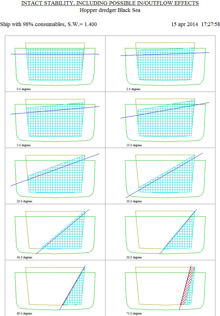
Hopper content at differente heeling angles
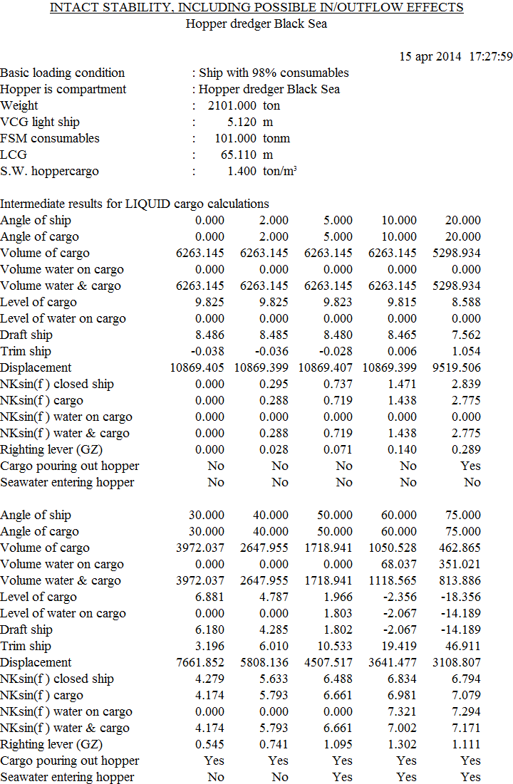
Detailed output of loading condition
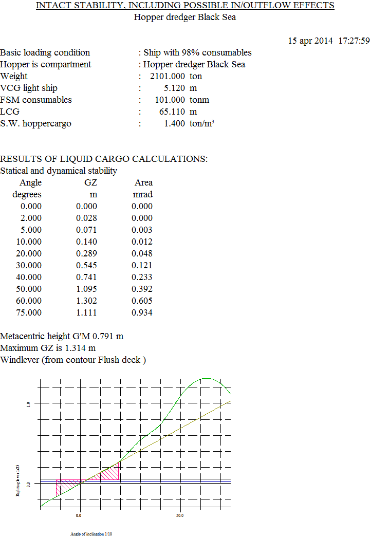
Table and plot of the GZ curve
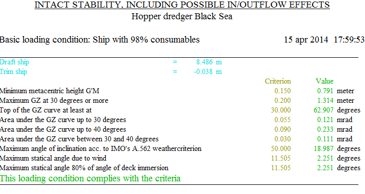
Stability summary