|
PIAS Manual
2024
Program for the Integral Approach of Shipdesign
|
|
PIAS Manual
2024
Program for the Integral Approach of Shipdesign
|
This action manages the connections between curves in a wireframe, which is a vital step in the conversion to a solid. Wireframe points represent the vertices in the boundary representation (B-rep) of the solid. The action is started from the menu [Objects]→[Wireframe Connections] or with the keys <Alt><O><C>.
The main purpose of this action is to determine which curves intersect and where they should be connected with a shared wireframe point. The most important criterion in this assessment is the value in the [Tolerance] field.
The process of searching for curve intersections is as follows.
It should be clear that there is no one-size-fits-all tolerance. Therefore it may be necessary to experiment a bit, and use [Undo] if results are not as intended. It may well be that most connections can be made automatically, but that a few cases remain that require manual attention.
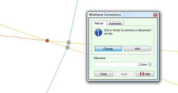
If existing wireframe points are present and the [Change] button on the [Manual] tab is depressed, wireframe connections to these points can be inspected, made and broken. Initially, moving the mouse pointer over wireframe points will highlight the curves that are connected to it. This way it is easy to scan for missing or incorrect connections, see the figure.
After clicking on a specific wireframe point, connected curves are selected. By clicking on a selected curve it will be disconnected from the wireframe point, and selecting an unselected curve will connect it if it runs by the wireframe point within the tolerance. So if a curve cannot be connected, try again after increasing the value in the [Tolerance] field. It is not necessary to hold <Ctrl> while selecting and deselecting curves.
A single new connection between two curves can be added by hand when the [Add] button on the [Manual] tab is depressed. Holding <Ctrl>, two curves should be selected that approach eachother within the given tolerance. A new wireframe point will be added to which the selected curves are connected. If more than two curves should intersect at the same point, the additional curves can be added afterwards as explained in Change existing connections.
Switching to the [Automatic] tab will initiate a search in which every curve in the wireframe is compared against every other curve. It is most practical to adjust the tolerance before switching the tab as changing the tolerance will restart the search. New wireframe points will be added for every curve intersection that is found for the given tolerance.
Before pressing [Apply], the generated connections may be inspected by changing back to the [Manual] tab, pressing the [Change] button and hovering over the generated wireframe points as described in Change existing connections.
If [Apply] is pressed while the [Automatic] tab is active, the action will immediately start a new search. This is harmless and the action can be closed at any time.
After connections have been generated, a validity check of the wireframe ( Checking the validity of wireframes) can report a high number of duplicate points. Two points on the same curve are considered duplicate if their separation is not more than 1 mm, which is a problem in the conversion to solid. Duplicate points can of course be resolved by deleting individual points from curves using [Delete] from the [Change the shape of a curve] action, but the problem can likely be avoided by connecting with a more appropriate tolerance, or by reducing the mean fairing deviation of all curves using [Bulk Change of All Curves]. The reason why too low a tolerance can produce double points, even though polylines in the input file run through identical coordinates, is the following.
If polylines have been converted to curves by the import procedure (see Intermezzo on polylines) then a non-zero mean fairing deviation will allow a deviation between the coordinates of the imported polyline and the faired curve, see Fair. Consequently, the search in steps 3. and 4. may yield an intersection point that deviates from the closest polyline coordinate. Since a connection between a wireframe point and a wireframe curve requires a point on the curve within the tolerance to the wireframe point, in step 5 a new point will be inserted on the curve if the distance to the existing point exceeds the tolerance. Likely, the new point is within 1 mm of the existing point, which qualifies them as double points. With a larger tolerance the existing point would have been within reach of the wireframe point, and it would have been connected, without the introduction of double points.