|
LOCOPIAS Manual Seagoing Vessels
2026
Loading Computer Software
|
|
LOCOPIAS Manual Seagoing Vessels
2026
Loading Computer Software
|
The lashing "mode" can be activated by pressing the [Lashing] on the top right of the container module. You can switch off the lashing mode by clicking on the button again. When the button is pressed, you can click on a 20' or 40' bay on a hatch. Such a bay can be fully or partially filled. When clicking on a loaded bay, you enter the lashing module window. A typical layout of the lashing module is shown below. Its elements are labeled with a number and described underneath.
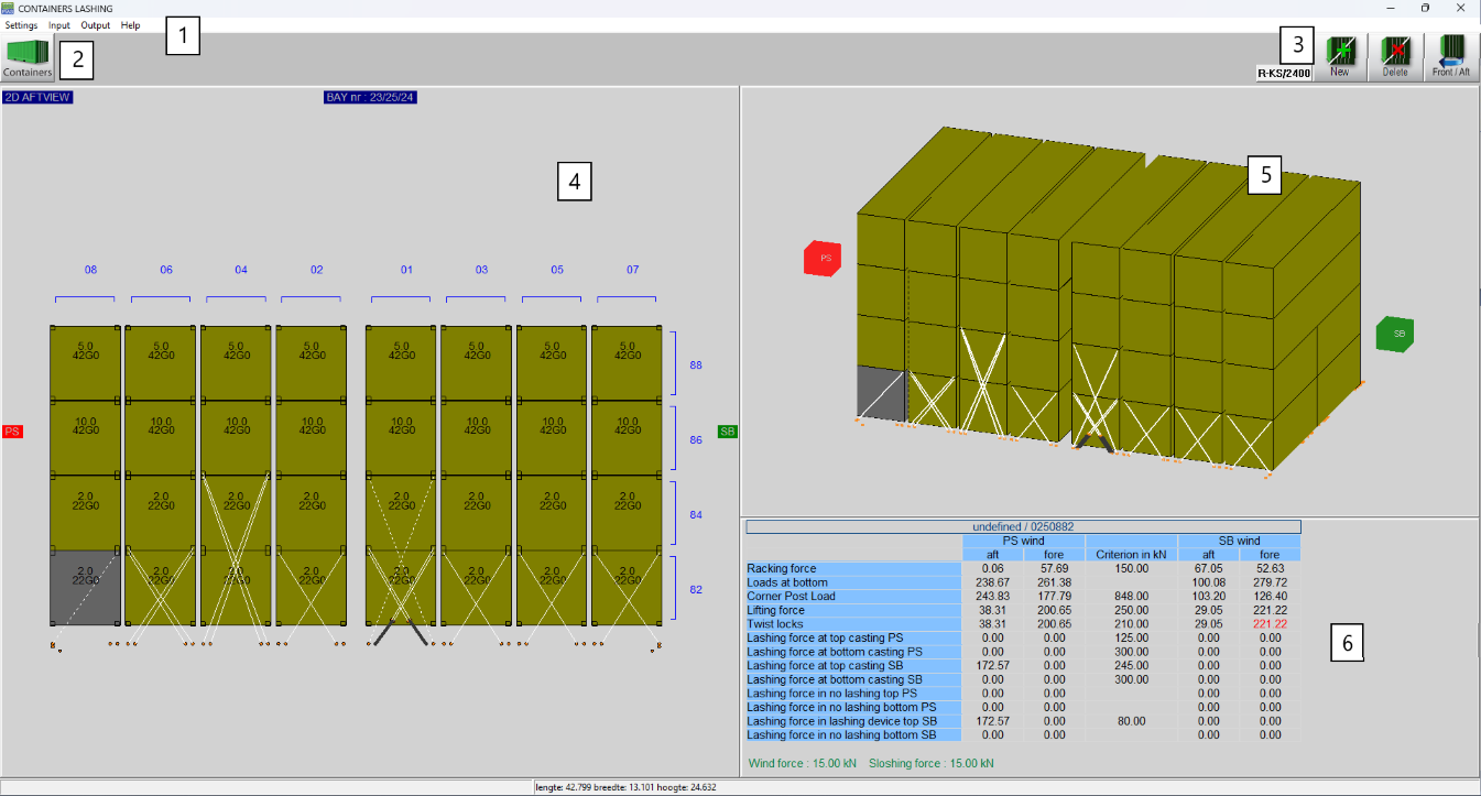
Basic functionalities are accessible through the menu bar.
This button navigates back to the [Container]-module.
Main functions of the Lashing module.
This is the main working window of the lashing module. All the functions happen through this window.
3D view of the selected baystack.
The basic entity of the lashing module is the "baystack", which is a set of any one type of container, or a combination of types, depending on their positioning in the bay on a hatch. The accepted container types are:
The 2D window 4 is for all the functions - make new lashing connections, remove existing ones, copy/paste and so on. The forces and accelerations are calculated automatically after each function (new/remove/copy/paste) for every container and its lashing connections. You can view the results either in the [Output] in the menubar in 1 for all the containers in the baystack, or separately for each container by selecting it. The module has pre-programmed maximum depending on the selected SDK. These values cannot be modified. The only modifiable values are the safe working loads (SWL) for the castings and the twistlocks, which can be found in the Settings in 1.
If any the forces does not comply with the limits provided by the SDK, the container will be drawn red in the 3D view in 5. When the non-complying container is selected, then the results window 6 will highlight in red the exceeding values.
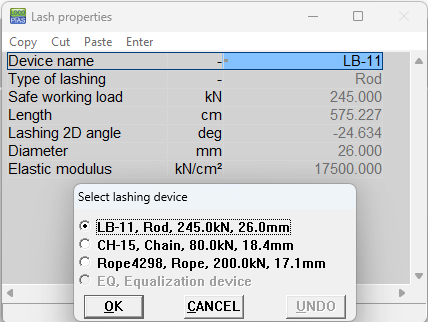
| Use this button to select a lashing device. By pressing on this button you will get a popup to choose from the defined lashing devices. If no device is selected the text on the button will be None. | |

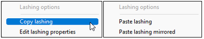
| Use this function to add a new lashing device or an equalization device. For a lashing device, left-click and hold on or around a casting corner. The new lash will immediately appear connected to the closest lashing plate. You can move the mouse pointer to the desired lashing plate and then release left-click mouse button. The new lashing is now established. For an equalization device, left click around or on a connection plate. Two new connection plates are now generated from a single plate, allowing for two lashings to connect to a single point. The equalization device will automatically rotate according to the lashing angles. |

| Use this function to delete an existing lashing connection or equalization device. Hover over and highlight the candidate connection, then left-click to remove it. If you remove an equalization device, any lashings that are connected to it will be automatically removed as well. |

| Use this function to switch between front and aft view. The 3D window rotates accordingly. The current viewing side is the mastering side and is noted on the top left of the window 4. |
There are two types of output :
By default, the synchronized lashing front and aft is enabled. The synchronized side is completely identical to the mastering side for all the functions described in Main functions. Any action on one side is automatically applied to the other one. Synchronized lashing can be disabled in the [Settings] in 1. If synchronized lashing is disabled, you can easily switch through aft and fore view to work independently. lashing_sync Synchronized lashing
The value of search depth in the [Settings] in 1 determines the number of connection plates that will be available for the lashings. That means that a search depth of 2 meters will show every connection plate 2 meters before the aftside of the baystack and 2 meters after the frontside of the baystack.
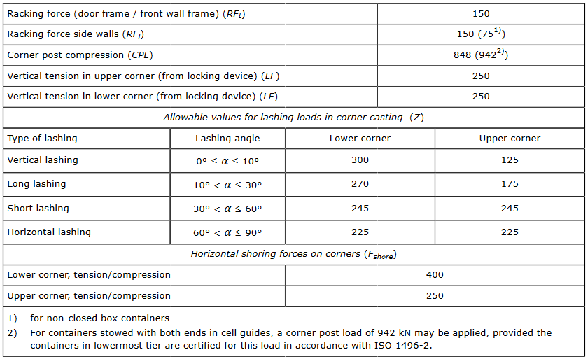
The SDK from DNV is Stowlash; The Stowlash 3D approach uses a 3D finite element calculation model, where each stack is treated separately without interaction.
All the results are compared against the following table, provided by DNV.
In the [Settings] in 1 you can select a reduction variant. There are pre-programmed routes with their reduction factor and an individual reduction factor. For weather dependent lashing, you can input the significant expected wave height and it will automatically calculate the reduction factor from the formula \(f_{wdl} = 0.3 + 0.1 * H_M\) where \(H_M\) is the significant wave height.
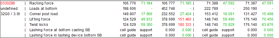
Cell guides support has been fully implemented for calculations with the DNV SDK : container stacks with both ends or with one end only supported by cell guides. In the results window in 4, the containers within the cell guides do not have results, but that is to be expected; If this is a stack with 20ft and/or 40ft containers where there is support in both ends from the cell guides, the corner post values of the lowest tier are compared to the stack loads. In the case of a 30ft stack, where there is support only on one end, the calculations run as usual. In the [Output] it will print cell guide support if the forces are non-zero on the end that is not supported by the cell guides, as shown below.
The SDK from Bureau Veritas is Veristar.
The results are calculated through a series of tests/load cases (LC), where the accelerations for upright and inclined conditions are derived according to BV rules:
In the [Settings] in 1 you can select a reduction variant. There are pre-programmed routes with their reduction factor and a special notation for weather dependent lashing, called Weather and Forecast (WAF). For the WAF reduction, you need to set the wave height and the wind speed.
The calculation results shown in 4 when a container is selected are a summary, showing the maximum value located through all four load cases. Fully detailed results per load case are printed in the [Output].