This module calculates the maximum allowable anchor chain forces during anchor handling, according to one of the following rules:
- Norwegian Maritime Directorate (NMD) from 2007: Guidelines for immediate measures on supply ships and tugs that are used for anchor handling.
- Bureau Veritas (BV) amendments January 2014, Pt. D Ch. 14 Sec. 2 Reg. 5: Additional requirements for anchor handling vessels.
- Intact Stability Code (IS) 2020, part B, section 2.7.
Input of specific ship data
The maximum allowable anchor chain forces are amongst others determined by a number of specific ship data, which are specified at the module for the definition of the hull shape and main dimensions, Hulldef. This module contains a menu option called Main dimensions and further ship parameters, which contains a sub menu Anchor handler characteristics. With this option an input window appears which contains the folowing parameters:
- The applicable stability regulation. The regulation chosen here is completely independent of any stability criterion chosen to verify the GZ-curve (as discussed in Stability criteria for intact stability and damage stability). It may seem overdone to choose regulations twice, however, these choices serve different purposes:
- In this module, the regulation is chosen that will be used for the maximum allowable forces. The regular GZ-curve of an individual loading condition does not need to be tested against this requirement (and cannot be tested against it because, as a rule, there is no actual anchor force included in the loading condition).
- The stability regulation chosen in the ordinary way will only be used for testing the GZ curve. As a rule, the standard Intact Stability Code (or another standard rule) is chosen for this purpose. The anchor chain force regulations in the regular set (see Seagoing) are rarely used, perhaps as a sample to verify an incidental loading condition (which then should include all components of an actual anchor chain force).
- Center of propeller above base, the vertical distance between the propeller center and the base line.
- Maximum chain force (wire tension), for which the winch capacity can be applied, or the holding capacity of the wire stopper if greater. If this figure cannot be determined, an ordinary ‘large’ value can be taken, for it is not used in the calculation as such. Its only purpose is to assist in determining the scaling factor in the polar plot.
- Wire is restricted at the extremity of the stern roller (only BV-2014 and IS-2020). This ‘extremity’ applies to the roller breadth. If this parameter is set to ‘yes’, two lines below the transverse distance between this extremity and CL should be given.
- Length from APP of aft side stern roller. Will speak for itself. Please consider that this terminology is aimed at a stern roller, however, a bow roller can be defined as well, in which case the longitudinal location of the forward side of the bow roller should be given here.
- ‘Restricting breadth from CL of the stern roller extremity’ (BV-2014 & IS-2020) or ‘breadth of the stern roller extremity from CL’ (NMD-2007), which means in both cases the transverse distance between a ‘physical restriction of transverse wire movement’ at the roller, and CL.
- Upper edge of stern roller from base line.
- Length from APP of guide pin or winch (BV-2014 & IS-2020). In this line, as well as the line below, primarily the guide pin is intended, however, if this is lacking than the particulars of the winch can be taken.
- Largest breadth from CL of guide pin or winch.
- Minimum dimensionless freeboard at the transom. Is a criterion that only applies to IS-2020, this is on the transom on CL the minimum freeboard divided by the length of the vessel. The regulatory standard is 0.005. The word “transom” has been used here because it is mentioned in the regulations. However, if the longitudinal position of the anchor roller is defined to be at the front of the vessel, this minimum freeboard is measured at the bow. Actually, the minimum freeboard is determined at the extremity of the anchor roller.
- Maximum bollard pull, in ton. Only for IS-2020, may be used for determining angle β depending from α and this bollard pull, according to reg. 2.7.2.1 from the code.
Finally, two remarks on the deck line:
- One of the stability criteria is that the deck line shall not be immerged under load of the chain force. For this it is important that the deck line is defined realistic, see Deck line for the deck line definition menu.
- Also for the IS-2020 criterion of the minimum dimensionless freeboard at transom — or at the bow, as discussed a few lines above — the deck line must be properly defined, in particular its aftmost (or foremost) point must actually be on CL.
Main menu of this module
Input for maximum anchor handling chain forces
In this menu the following parameters can be defined:
- Start, end and increment for the displacement, in metric tons, for the tables or diagrams to be produced.
- Similarly the start, end and increment for KG', the (virtual) center of gravity, in meter.
- Including graphs. This module will produce output in tables, which are always printed, and optional in diagrams (only NMD-2007 and BV-2014).
- Only for IS-2020: whether angle β should be fixed according to the formulas of reg. 2.7.2.1 of the code, or that a series of βs must be calculated (as can be specified in the last two rows of this menu). The latter choice is not according to the code, but can be used to explicitly investigate the relationship between maximum allowable anchor force and β.
- Whether tables for all individual stability criteria have to be included as well. All requirements contain multiple independent stability criteria, which all have to be complied with. As such, it is not required to determine the maximum anchor forces for each individual criterion, however, for the ship designer such a table might be handy, because it may give an indication on the most critical stability aspect, and action may be taken to improve that particular stability property. By the way, it is advised not to include such tables per individual stability criterion with ship delivery documents. Not that there is something wrong with them as such, but there is always the risk that somebody does not recognize the background of such a table, so that it may raise confusion or misunderstanding.
- The initial trim [m]. The calculation can be performed for one or more trims. Multiple trims can be defined at the second option in the main menu of this module (or, altenatively, with <Enter> in this cell). If no trims have been specified there, at this menu option a single trim can be specified. This trim is called initial trim, because with the free-to-trim effect switched on, the actual trim at larger angles of inclination may vary.
Furthermore, a number of regulation-specific parameters can be entered. For NMD-2007 these comprise start, end and increment of the chain angle (in degrees), which is the angle between chain or wire and the longitudinal plane. And for BV-2014 & IS-2020 the end value and increment — the start value is always zero — of the angles α and β, respectively the angle between the wire and the longitudinal, and between the wire and the horizontal plane, as depicted in the figure below.
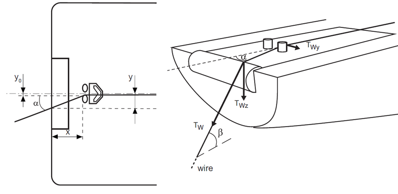
Definitions of angles, BV-2014 and IS-2020.
Calculate and print maximum anchor handling chain forces
Several output options can be choosen, from which two examples are pasted below. The output may contain:
- For each defined chain angle a table and (possibly) a diagram with on the horizontal axis the KG', on the vertical axis the maximum allowable anchor chain force, while for each desired displacement a curve is plotted which indicates the relation between KG' and anchor chain force.
- For each chain angle a table with the maximum allowable chain force for each individual stability criterion. A short description of the applicable crition is printed in the heading of each table.
- Depending on the applied regulation: a table and (possibly) a diagram with the lowest chain force for seris of chain angles.
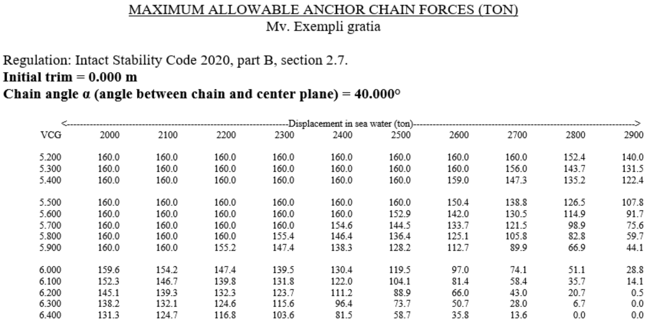
Table of maximum allowable anchor chain forces (IS-2020).
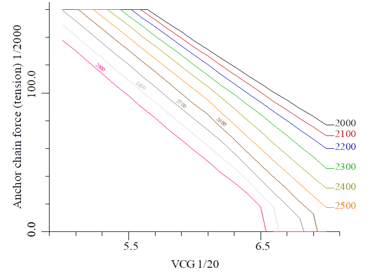
Diagram of maximum allowable anchor chain forces (BV-2014).
Polar diagram with maximum allowable anchor chain forces for a particular loading condition
In this module, Maxchain, statical tables and diagrams of maximum anchor chain forces are computed. However, it is also possible to have each intact loading condition — as computed with Loading, Settings polar diagram anchor handling chain forces — accompanied by a specific polar plot of maximum chain forces If desired, the following approach is adopted:
- The anhor-handling input data from Hulldef (see the first section of this chapter) are used.
- Chain angles and VCGs as specified for this Maxchain module play no role. The polar diagram is always calculated from 0° to 90°, based on the loading condition where that polar plot belongs to.
- Anchor chain forces should not be included in weight items of the loading condition, for it is the intention of this PIAS module to determine the maximum anchor chain force automatically.
For each loading condition such a diagram can be produced, where radial the maximum allowable anchor chain forces (in ton) can be read for different anchor chain angles. In a calculation according to IS-2020 the output is as shown in the figure below, here is only a single line that indicates the separation between allowed (green) and prohibited area (red) as a function of α The second polar diagram shows the output of a calculation according to BV-2014, this contains per β a line of maximum allowable anchor chain force.
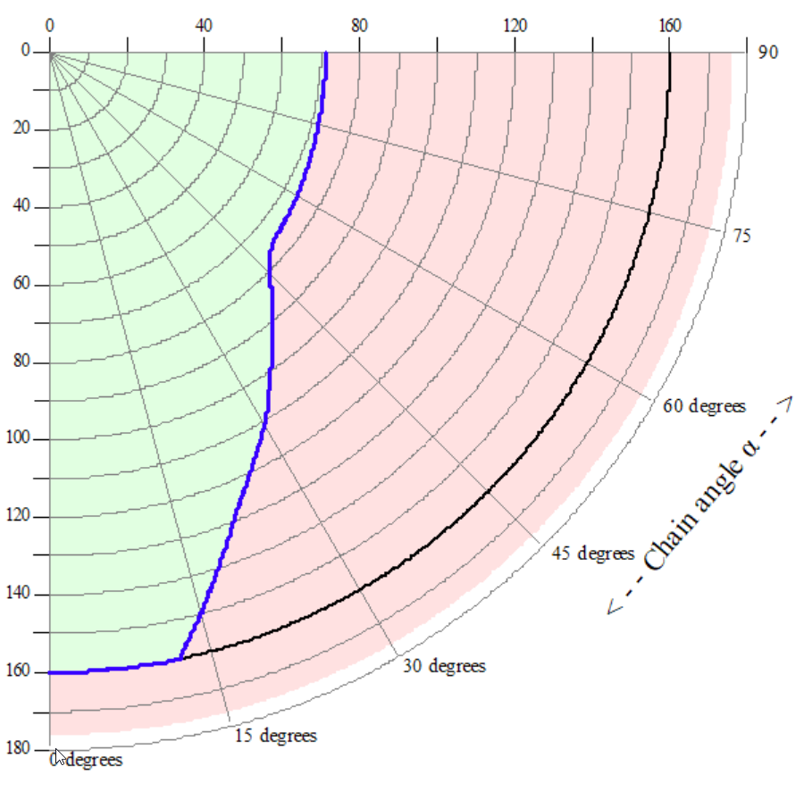
Polar plot of maximum allowable anchor chain forces according to IS-2020.
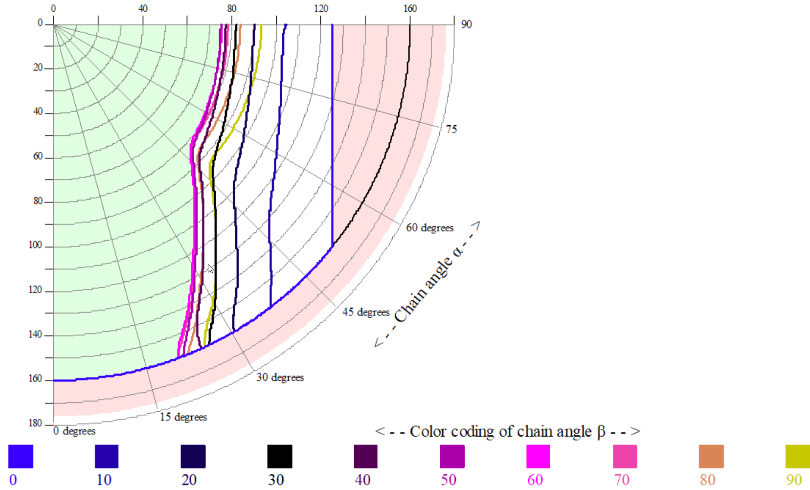
Polar plot of maximum allowable anchor chain forces, according to BV-2014.