|
PIAS Manual
2026
Program for the Integral Approach of Shipdesign
|
|
PIAS Manual
2026
Program for the Integral Approach of Shipdesign
|
This action, started with the keys <Alt><P><E>, enables the user to project a polycurve of an active solid or wireframe onto other active solids. This can also be viewed as intersecting a solid with a (possibly) curved surface, defined by an extrusion of a polycurve in a defined direction. The projection can be parallel or a point-projection.
This action does not make use of curved surfaces, the new polycurve will only have points at intersections with existing curves in the model. Therefore, it may be desirable to add planar polycurves prior to projection to achieve sufficient accuracy, see [New Planar Polycurve by Intersection].
Note that if there is just one solid present in the model, no polycurve can be selected because projections of polycurves onto its own solid are not supported. You can however create and manipulate an auxiliary polycurve and project that.
If the polycurve to be projected is not already present in another solid or wireframe, it may be desirable to create a new polycurve for the occasion, independent from any solid. An auxiliary polycurve can be created from within this action by pressing the button [Manipulate New Auxiliary Polycurve]. Polycurves created this way will appear in a wireframe with the name "Projection Polycurves". The new polycurve will have an initial shape of a straight line running diagonally through the model. Most likely this is not the desired shape and therefore the current action is interrupted and intermediate manipulation of the auxiliary curve is automatically started; see [Change the shape of a curve]. As soon as that action is closed, the projection action is continued for further configuration.
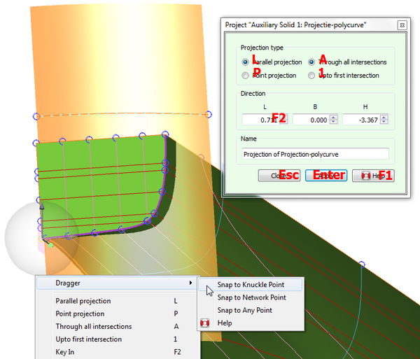
While configuring a parallel projection of the polycurve, a translucent preview surface is shown through the selected polycurve in a given direction, intersecting the solids in the model. This surface shares the color of spatial polycurves, as the resulting projection will be one or more spatial polycurves running along the intersection between the preview surface and active solids.
The direction vector can be keyed in on the action panel directly, and is visualized by a dotted line in one of the ends of the selected polycurve. A dragger allows graphical manipulation of this vector: by dragging the end of the dotted line the direction is changed, and by dragging the start the vector is simply translated without changing its direction (see Dragging a direction vector).
In some cases a straight line exists in the model that represents the direction in which the projection should be applied. Alignment like this is easily accomplished using the dragger snap functionality discussed in Snapping to other points in the model, by translating the direction vector to the start of the straight line and selecting the end point as its direction.
When point-projection is selected, the preview surface converges through a single point. Again, this through-point can be keyed in manually, or translated graphically using the dragger.
Both the direction vector and the through-point are persistent across applications of the action, so that multiple polycurves can be projected successively using the same projection.